Debris flow drainage channel with step pool structure and its applications

a technology of step pool and drainage channel, which is applied in the direction of artificial water canals, marine site engineering, and dykes, etc., can solve the problems of increasing the maintenance cost of the operating period, reducing the service life of the drainage channel, and absorbing the debris flow intensely, so as to reduce the cost of later-stage maintenance, reduce the service life of the drainage channel, and regulate the flow velocity of the debris flow

Active Publication Date: 2017-12-05
INST OF MOUNTAIN HAZARDS & ENVIRONMENT CHINESE ACADEMY OF SCI
View PDF6 Cites 2 Cited by
  • Summary
  • Abstract
  • Description
  • Claims
  • Application Information

AI Technical Summary

Benefits of technology

[0004]To overcome the disadvantages of prior methods, i.e., drainage channel bottoms being seriously damaged and being unable to operate normally as well as the high later-stage maintenance costs caused by the intense abrasion and scouring actions of debris flows subject to large gully bed longitudinal slopes and the frequent occurrence of debris flows, the invention provides a debris flow drainage channel with a step pool structure. This structure provides a large degree of safety, lower later-stage maintenance costs, and applicability to debris flow gullies with large gully bed longitudinal slopes.
[0006]The invention provides a debris flow drainage channel with a step pool structure, which consists of a drainage channel bottom and drainage channel side walls arranged on both sides of the drainage channel bottom, wherein the drainage channel bottom consists of multiple fully lined step sections arranged at certain intervals and a pool section filled between the upstream and downstream step sections. The step section consists of an upper indented sill located upstream, a lower indented sill located downstream and a fully lined baseplate connecting the upper indented sill with the lower indented sill. The pool section consists of a cable net cage bottom protection, a cable net cage buffer layer and block stones, wherein the cable net cage buffer layer is arranged above the cable net cage bottom protection and clung to the upper indented sill of the downstream step section. The block stones are arranged in a space defined by the side walls, the cable net cage bottom protection, the lower indented sill of the upstream step section and the cable net cage buffer layer. The cable net cage bottom protection and the cable net cage buffer layer are structurally formed by wrapping block stones in a cable net. Finally, the top surface of the pool section is flush with the highest point of the downstream step section, and the length L4 of the pool section is less than the length L1 of the step section. The main function of the pool section is to dissipate some of the kinetic energy of debris flow movement, regulate the flow velocity of a debris flow and control the scouring of a debris flow body at the bottom of the drainage channel. The pool is the space defined by the side walls, the cable net cage bottom protection, the lower indented sill of the upstream step section and the cable net cage buffer layer. The block stones filling in the pool interact with the debris flow body to dissipate the kinetic energy of the debris flow, thereby achieving the purpose of regulating the flow velocity of the debris flow and controlling the scouring of the debris flow at the channel bottom and the abrasion at the step sections. The cable net cage bottom protection can absorb the impact energy of the debris flow and inhibit the exchange between the debris flow body and the foundation soil body of the channel bottom. In particular, it can control the foundation soil body to participate in debris flow activities, thereby controlling the scouring of the debris flow body at the drainage channel bottom, ensuring normal drainage function and reducing the later-stage maintenance costs. Moreover, the cable net cage buffer layer can produce a buffer effect on the horizontal impact force, borne by the step sections, of the debris flow body.
[0012]To better achieve equilibrium drainage of debris flows under the condition of large gully bed longitudinal slopes and avoid the occurrence of intense scouring and silting, the ratio of the width B of the drainage channel bottom to the depth H (i.e., the effective height of the side wall) of the drainage channel is greater than or equal to 2.0, i.e., B / H≧2.0. The large gully bed longitudinal slope generally refers to the fact that the average gully bed longitudinal slope i0 is greater than or equal to 0.20, i.e., i0≧0.20. The debris flow drainage channel with a step pool structure provided by the invention is particularly suited to the drainage of debris flows with an average gully bed longitudinal slope i0 of 0.2-0.4.
[0013]Compared with the state of the art, the debris flow drainage channel with a step pool structure provided by the invention provides the following benefits: by fully utilizing the step pool structure, the debris flow and the block stones interact to dissipate some of the kinetic energy of the movement of the flow and to regulate the flow velocity of the debris flow. In addition, a cable net cage is utilized to absorb the impact energy of the debris flow and inhibit the exchange between the debris flow body and the foundation soil body of the channel bottom, thereby controlling the scouring of the debris flow body at the channel bottom. This ensures normal drainage function and reduces later-stage maintenance costs; moreover, compared with fully lined drainage channels, the debris flow drainage is safer under steep slope conditions, project reliability is greatly improved, and the later-stage maintenance costs are reduced by 50-80%. Compared with ground-sill soft-foundation energy-dissipating debris flow drainage channels, project reliability is greatly improved, and the later-stage maintenance costs are reduced by 30-50%. Compared with cage-lined drainage channels, the later-stage maintenance costs are reduced by 20-40%.

Problems solved by technology

For a debris flow with a large or steep gully bed slope, if the debris flow is discharged using a commonly used fully lined debris flow drainage channel (commonly known as a V-type drainage channel), a situation occurs in which the debris flow intensely abrades the channel bottom because the debris flow velocity in the channel is too high.
This greatly reduces the service life of the drainage channel, and the maintenance cost of the operating period is increased.
This threatens the safety of the ground sills, thereby resulting in the destruction of the drainage channel.
When the distance between ground sills is small, the project investment will be greatly increased, and the safety of the ground sills cannot be ensured.
However, for high-frequency debris flows, because the abrasion resistance and impact resistance of the wall of the energy dissipation structure are limited, a situation easily occurs in which the wall of the energy dissipation structure is damaged, and thus, the control effect on the debris flows is greatly reduced.

Method used


Image

  • Debris flow drainage channel with step pool structure and its applications
  • Debris flow drainage channel with step pool structure and its applications
  • Debris flow drainage channel with step pool structure and its applications

Examples


embodiment 1

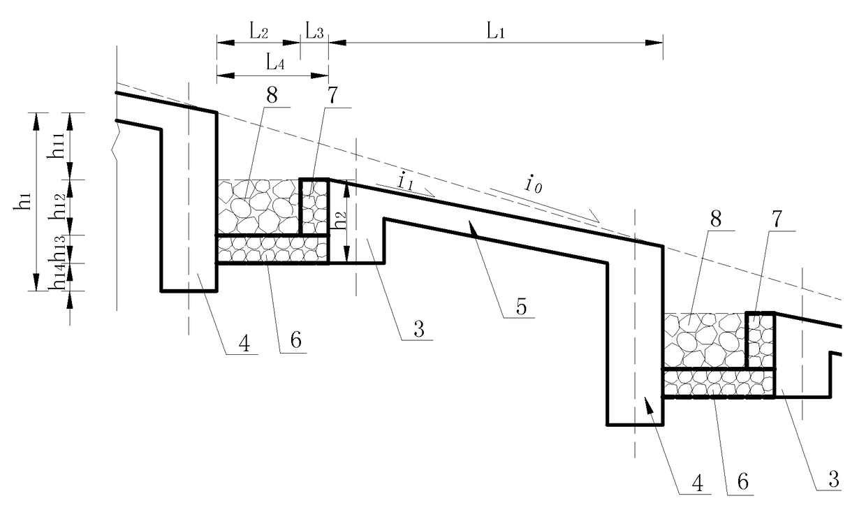
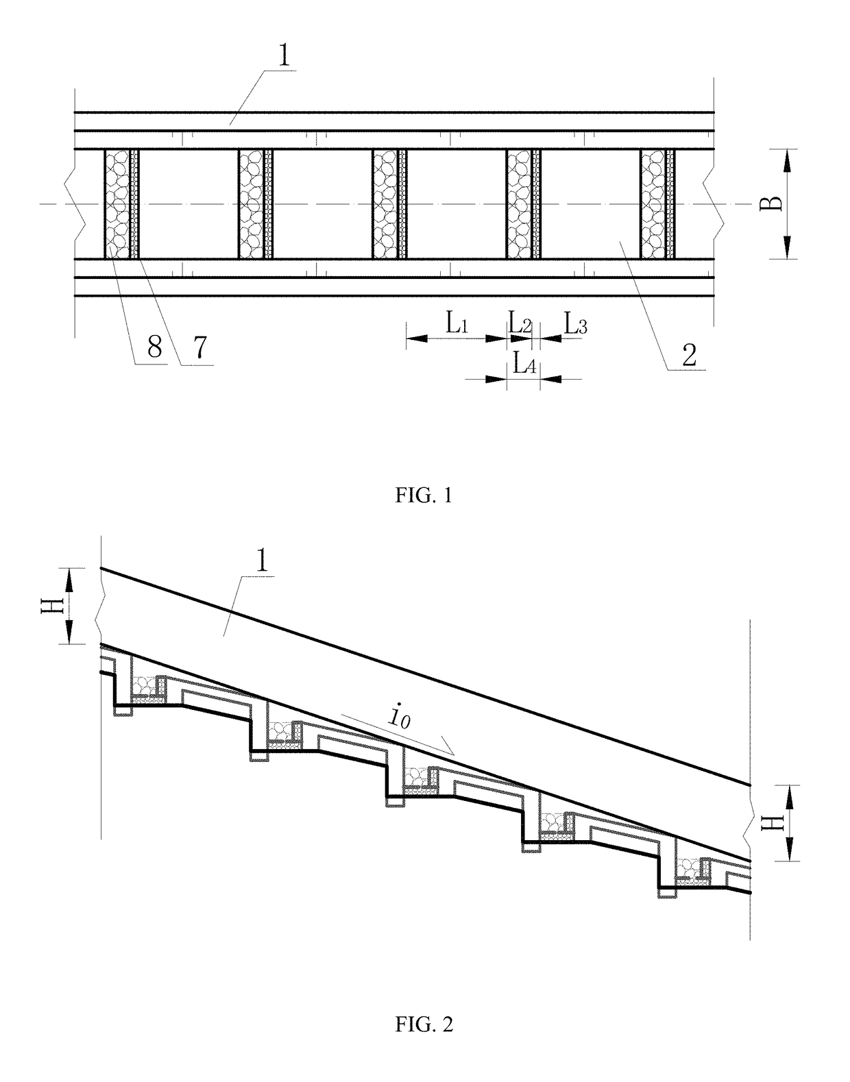
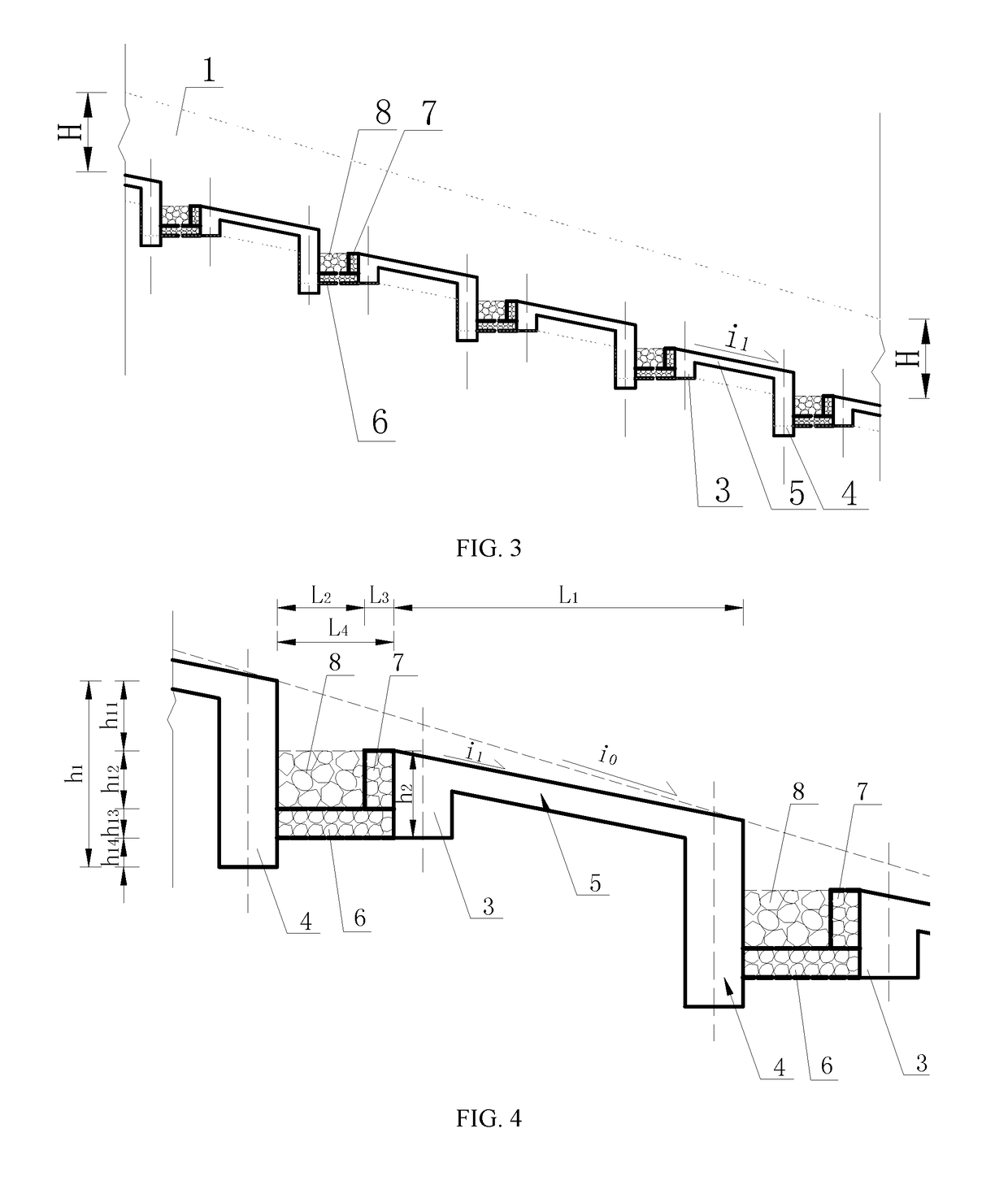
[0023]As shown in FIG. 1, FIG. 2, FIG. 3, FIG. 4, FIG. 5 and FIG. 6, when the area of the drainage basin of some debris flow gully is 1.78 km2, to prevent debris flow disasters, one silt arrester is designed to be placed in the middle of the drainage basin, and a drainage channel with a length of 240 m is designed to be built on a deposition fan. For the drainage channel, the average gully bed longitudinal slope i0 of the channel bottom is 0.40, the flow rate of the drained debris flow is 96 m3 / s, and the density is 21.5 kN / m3, to control the intense abrasion and scouring actions of the debris flow, the debris flow drainage channel with a step-pool structure is adopted. The debris flow drainage channel with a step pool structure consists of a drainage channel bottom and drainage channel side walls (1) arranged on both sides of the drainage channel bottom, wherein the drainage channel bottom consists of multiple fully lined step sections. Two sections are arranged at a given interval...

embodiment 2

[0030]As shown in FIG. 1, FIG. 2, FIG. 3, FIG. 4, FIG. 5 and FIG. 6, when the area of the drainage basin of a given debris flow gully is 8.6 km2, to prevent debris flow disasters, three silt arresters are designed to be arranged in the middle of the drainage basin, and a drainage channel with a length of 480 m is designed to be built on a deposition fan. For the drainage channel, the average gully bed longitudinal slope i0 of the channel bottom is 0.20, the flow rate of the drained debris flow is 265 m3 / s, and the density is 15 kN / m3, to control the intense abrasion and scouring actions of the debris flow, and the debris flow drainage channel with a step pool structure is adopted. The debris flow drainage channel with a step pool structure consists of a drainage channel bottom and drainage channel side walls (1) arranged on both sides of the drainage channel bottom, wherein the drainage channel bottom consists of multiple fully lined step sections (2) arranged at a given interval an...


PUM


Abstract

A debris flow drainage channel is provided. The debris flow drainage channel is applicable to debris flows with large gully bed longitudinal slopes. The debris flow drainage channel has an upstream step section and a downstream step section. The debris flow drainage channel also has a step pool disposed between the upstream step section and the downstream step section. The pool section has a cable net cage bottom protection, a cable net cage buffer layer and block stones.

Description

FIELD OF THE INVENTION[0001]The present invention relates to a debris flow prevention and control technology, in particular, a debris flow drainage channel with a step pool structure, which is applicable to debris flow gullies with steep gully bed longitudinal slopes.BACKGROUND OF THE INVENTION[0002]Debris flow disasters are one of the main types of geological disasters experienced worldwide, especially in China. With the economic development of mountainous areas and the development of western China, the demands on debris flow project management are becoming increasingly vigorous. Drainage channels, as one of the main types of debris flow prevention and control projects, are widely applied in debris flow hazard mitigation.[0003]Following the Wenchuan Earthquake, massive collapses and landslides have provided rich solid material sources for the formation of debris flows and a large number of debris flows have been triggered in gullies with steep gully bed slopes of greater than 0.20 ...

Claims


Application Information

Patent Timeline
Patent Type & Authority Patents(United States)
IPC IPC(8): E02B3/10E02B5/08E02B8/02E01F7/04E02B5/00
CPCE02B3/10E01F7/04E02B8/02E02B5/085E02B5/00
Inventor CHEN, XIAOQINGWEI, FANGQIANGCHEN, JIANGANGYOU, YONGWANG, TAO
Owner INST OF MOUNTAIN HAZARDS & ENVIRONMENT CHINESE ACADEMY OF SCI
Why Eureka
Try Eureka