Automatic system for controlling appliances

a technology of automatic control and appliances, applied in adaptive control, process and machine control, instruments, etc., can solve the problems of not being designed to prevent overload, and not providing automatic optimization of domestic electric power consumption. , to achieve the effect of reducing power consumption

Active Publication Date: 2017-12-05
TELECOM ITALIA SPA
View PDF6 Cites 6 Cited by
  • Summary
  • Abstract
  • Description
  • Claims
  • Application Information

AI Technical Summary

Benefits of technology

[0012]In view of the state of the art outlined in the foregoing, the Applicant has faced the problem of how to provide a system and a method for managing house appliances which is capable of automatically optimizing the domestic power consumption and preventing the occurrences of overloads in a relatively short time, without requiring high computational resources.
[0020]According to an embodiment of the invention, the at least one control unit is further configured to control the house appliances in order to reduce the power consumption of the currently active house appliances and / or to deactivate at least one of the currently active house appliances if the power consumption of the currently active house appliances is higher than a guard threshold lower than the maximum power threshold of the power grid.

Problems solved by technology

The Applicant has found that the above mentioned solutions known in the art are affected by drawbacks, and / or are not efficient.
The system disclosed in patent application WO2009 / 097400 does not provide for automatically optimizing the domestic electric power consumption.
Moreover, the system of WO2009 / 097400 is not designed to prevent overloads.
In any case, a method based on a brute-force approach such as the one proposed by Onur Derin and Alberto Ferrante requires a high amount of time to provide satisfactory results, and thus it is scarcely suitable to be used in dynamic scenarios, such as the management of domestic electric power consumption.

Method used


Image

  • Automatic system for controlling appliances
  • Automatic system for controlling appliances
  • Automatic system for controlling appliances

Examples


Embodiment Construction

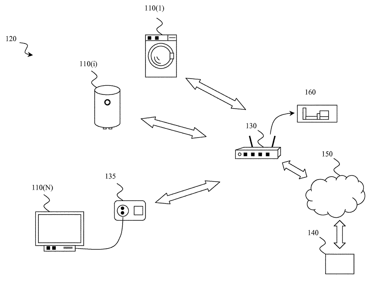
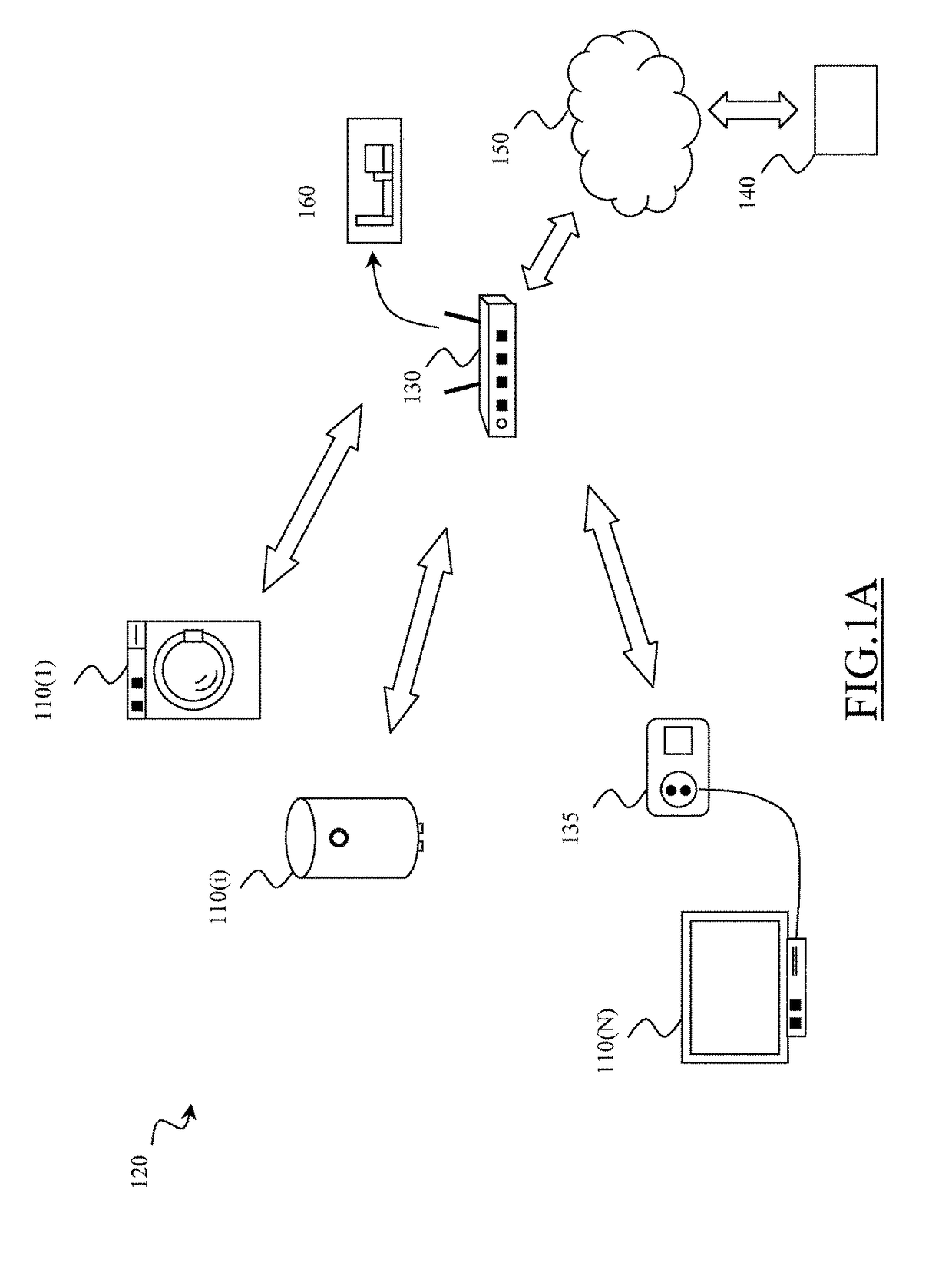
[0038]With reference to the drawings, FIG. 1A illustrates a system 100 for monitoring and controlling house appliances 110(i) (i=1 to N) which are supplied by the line power provided by the power grid in a domestic area 120, such as a house, according to an embodiment of the present invention. A local control unit 130 is located in or in the proximity of the domestic area 120 for managing the operation of the system 100 by carrying out a power managing procedure which will be described in detail in the following of the description. For this purpose, the local control unit 130 is wirelessly interfaced with each house appliance 110(i) for receiving therefrom data regarding its power consumption, and for correspondingly transmitting thereto commands for managing its operation.

[0039]The local control unit 130 may be located in a hardware processing unit, such as a domestic wi-fi station (e.g., an ADSL router), and the power managing procedure may be carried out by running an application...


PUM


Abstract

A system for managing house appliances supplied through a power grid is provided. Each house appliance operates according to at least one corresponding operative mode. Each operative mode comprises a sequence of operative phases. The system comprises at least one control unit interfaced with the house appliances for exchanging data. The at least one control unit collects power profile data comprising timing and electric power consumption data of each operative phase of each operative mode of the house appliances; generates a time schedule of the house appliances operations by distributing in time the execution of the operative phases thereof such that total power consumption of house appliances is kept under a maximum power threshold of the power grid; and controls the operation of the appliances based on the time schedule. The at least one control unit is configured to generate the time schedule by exploiting a Particle Swarm Optimization approach.

Description

BACKGROUND OF THE INVENTION[0001]Field of the Invention[0002]The present invention relates to a system and a method for monitoring and controlling the electric power consumption of home appliances supplied by the line power.[0003]Description of the Related Art[0004]Nowadays, the management of the domestic electric power consumption is become a very complex issue.[0005]Indeed, domestic electric power consumption is highly variable. Typically, during a working day, highest electric power consumptions mainly occur during morning and evening, while during weekends electric power consumption is more evenly distributed. Other factors may strongly influence the domestic power consumption, such as for example the holidays and seasons of the year. Moreover, if on one hand the domestic electric power demand has reached higher and higher peak levels, on the other hand environmental and economical reasons have brought to the diffusion of residential renewable electric power generation units, wh...

Claims


Application Information

Patent Timeline
Patent Type & Authority Patents(United States)
IPC IPC(8): G05D11/00H02J3/00G01D4/00H04L29/08G05B13/02
CPCH02J3/00G01D4/00G05B13/021H04L67/125H01L2924/0002H01L2924/00Y04S40/18G01D2204/28
Inventor BOREAN, CLAUDIOGRASSO, ENNIO
Owner TELECOM ITALIA SPA
Why Eureka
Try Eureka