
Cannula assembly

a cannula and assembly technology, applied in the field of cannula systems, can solve the problems of hindering visualization, turbulent saline flow within the joint, increased bleeding, etc., and achieves the effects of reducing the surgical failure rate, improving patient outcomes, and facilitating surgeon adaptation

Inactive Publication Date: 2017-12-12
ARTHROPTICS L L C
View PDF2 Cites 0 Cited by
  • Summary
  • Abstract
  • Description
  • Claims
  • Application Information

AI Technical Summary

Benefits of technology

The present invention is a surgical system that uses a cannula-camera system to provide multiple viewing angles of the surgical site. This added visualization helps the surgeon have better feedback and reduces the risk of surgical failure. The cannula has a lumen portion with a main lumen and a smaller secondary lumen. A modified trocar is inserted into the lumen portion. The cannula is then inserted into the surgical site in a similar way to current cannulas for easy surgeon adaptation. The imaging device is housed in a long tube and is inserted through the designed secondary lumen on one side of the cannula. This allows the imaging device to provide visualization without obstructing the main lumen for the use of tools. The patent text describes a system that allows multiple cannulas to be used simultaneously within the joint to provide tool interaction and additionally video output with multiple views to a monitor.

Problems solved by technology

Pressure fluctuations may occur, resulting in turbulent saline flow within the joint and increased bleeding that can hinder visualization.
In addition, the single field of view provided by the arthroscope is limited, which may result in imprecision, and consequently lower the surgical success rate.
In addition, current technology does not allow for instrumentation and visualization from the same portal, such that the ideal view afforded by the arthroscope may often need to be compromised to permit instrumentation of the pathology.
These visualization setbacks, along with a lack of standardization in the current surgical technique, can lead to a surgical failure rate that exceeds 40% in certain joints.

Method used


Image

  • Cannula assembly
  • Cannula assembly
  • Cannula assembly

Examples


Embodiment Construction

[0019]The following description of the preferred embodiment(s) is merely exemplary in nature and is in no way intended to limit the invention, its application, or uses.

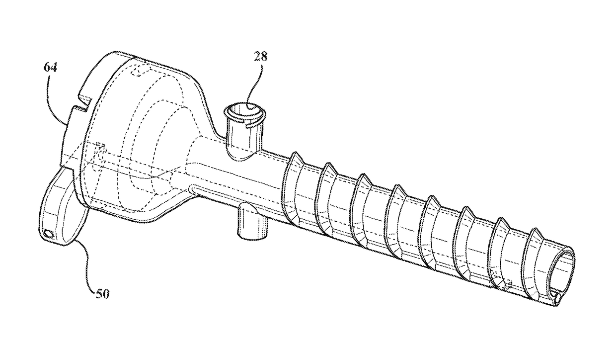
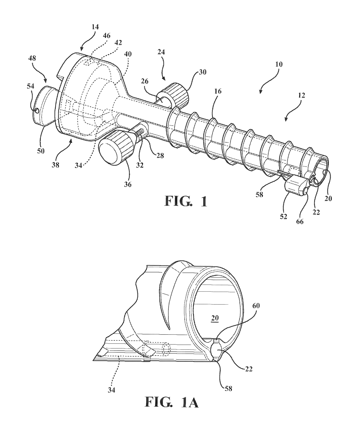
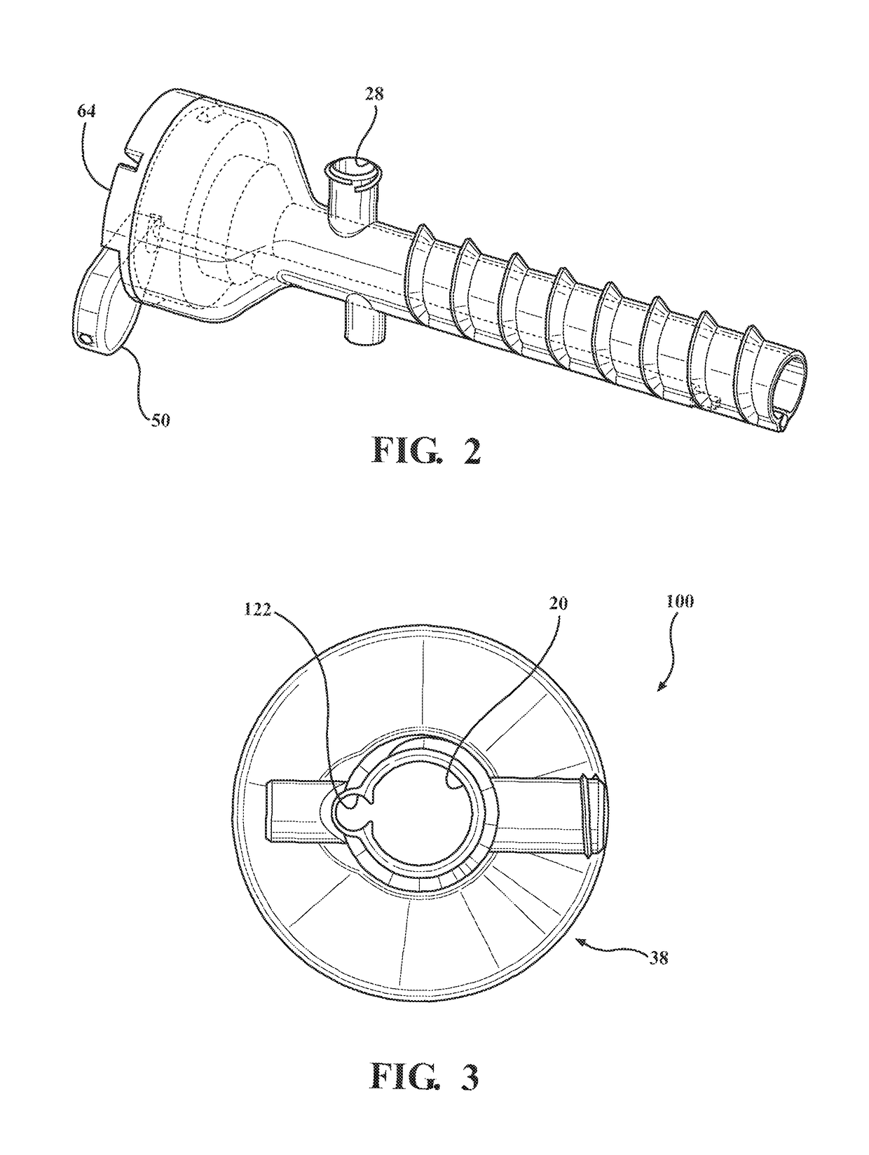
[0020]Referring to FIGS. 1-11 generally, in accordance with the present invention, there is provided a cannula assembly generally shown at 10 for surgical procedures such as performed within joint areas of the body or other areas.

[0021]The cannula assembly 10 includes a cannula generally indicated at 12 that is threaded and a cap portion generally indicated at 14. A trocar generally shown at 18 (FIG. 9) is selectively inserted into the cannula assembly 10 for inserting the assembly 10 into a body cavity, as will be explained in further detail below. The threads 16 on the external surface of the cannula 12 generally assist with holding placement in the body cavity.

[0022]The cannula assembly 10 includes a lumen portion with at least two adjoining lumen comprising a main lumen 20 and at least one secondary lumen 22. Eith...


PUM


Abstract

A cannula assembly including a camera system to help provide multiple viewing angles of a surgical site. This added visualization provides the surgeon with more comprehensive feedback during the surgical procedure, leading to better patient outcome and a reduction in the surgical failure rate. The cannula has a main lumen and a smaller secondary lumen and is insertable into the surgical site for easy surgeon adaptation. The camera is coupled to the secondary lumen toward the side of the cannula. This allows the camera to provide visualization without obstructing the main lumen for the use of tools. The camera wiring runs through a long tube connected to the camera and through a handle at the end of the tube without blocking access to the surgical site.

Description

CROSS-REFERENCE TO RELATED APPLICATION[0001]The instant application claims priority to U.S. Provisional Patent Application Ser. No. 61 / 954,232 filed Mar. 17, 2014. The disclosure of the above application is incorporated herein by reference.FIELD OF THE INVENTION[0002]The present invention relates to a cannula system with at least a pair of lumen and an imaging device used for surgical procedures.BACKGROUND OF THE INVENTION[0003]Arthroscopic surgery is increasingly being preferred over open surgery due to its minimally invasive nature and shorter post-surgery recovery time. Current estimates state that there are 4 million arthroscopic procedures each year in the United States. During each procedure, surgeons typically use 2 to 3 cannulas: one is occupied by the arthroscope and the others are utilized for the insertion of surgical tools. The arthroscope provides only a single, two-dimensional vantage point of the joint during surgery. If the surgeon wants to view the surgical site fro...

Claims


Application Information

Patent Timeline
Patent Type & Authority Patents(United States)
IPC IPC(8): A61B1/05A61B1/00A61B90/00A61B17/34
CPCA61B1/00183A61B1/00135A61B1/05A61B17/3417A61B17/3421A61B17/3474A61B90/361A61B2217/007A61B2017/349A61B2017/3445A61B2017/3454A61B2017/3458A61B2217/005
Inventor MACDONALD, JORDANCALYORE, CHRISTIANLEE, YI-TINGRAVI, NANDINIALIMASA, ADRIENNE
Owner ARTHROPTICS L L C
Learn More