Pseudo flexure for disk drive and method of testing electronic circuit for disk drive

a technology of electronic circuit and disk drive, which is applied in the direction of functional testing of recording heads, instruments, and integrated arm assemblies, etc., can solve the problems of only being able to perform testing, unable to accurately contact the probe of the test apparatus (i.e., perform probing) on the pads arranged in a narrow range, and getting more and more difficult to perform probing stably

Active Publication Date: 2017-12-12
NHK SPRING CO LTD
View PDF14 Cites 5 Cited by
  • Summary
  • Abstract
  • Description
  • Claims
  • Application Information

AI Technical Summary

Benefits of technology

[0011]An embodiment relates to a pseudo flexure for a disk drive comprising a flexure body portion including a conductive circuit portion, and a test coupon which electrically conducts to the conductive circuit portion, in which the test coupon comprises: a substrate formed of a first metal such as stainless steel; a dielectric layer formed of an electrically insulating resin, and having a first surface and a second surface, in which the first surface overlaps the substrate; a metal layer formed of a second metal such as copper whose electrical resistance is different from that of the first metal, and arranged on the second surface of the dielectric layer; a pair of input-side terminal portions electrically connected to write conductors of the conductive circuit portion; a pair of pads for probing provided at a detection position; and a pseudo element circuit formed between the input-side terminal portions and the pads for probing. The pseudo element circuit comprises a main circuit section having a double-layered conductor structure, and an adjusting section having a single-layered conductor structure. The main circuit section includes a first pattern conductor formed of the first metal such as stainless steel, and a pair of second pattern conductors, which is formed of the second metal such as copper, overlaps the first pattern conductor with the dielectric layer interposed therebetween, and is connected to the first pattern conductor. In contrast, the adjusting section includes a pair of linear conductors arranged along the dielectric layer, and the linear conductors are electrically connected to the second pattern conductors, respectively. Although an example of the first metal is stainless steel, the first metal may be other than stainless steel. Further, although an example of the second metal is copper, the second metal may be other than copper.

Problems solved by technology

Therefore, it is getting more and more difficult to accurately contact the probe of the test apparatus (i.e., perform probing) on the pads arranged in a narrow range.
For this reason, the magnetic head is swung easily at the time of measurement, and performing the probing stably is difficult.
Further, there is also a problem that in order to test the electronic circuit by using the magnetic head, the testing can only be performed when the magnetic head and the suspension are both completed.
However, adjustment of the resistance (R-component) is difficult in such a pseudo head probe device, and obtaining a desired inductance value is also difficult.
Also, variations of the electrical properties are relatively large in this type of handmade pseudo head probe device, and evaluating the test result is sometimes hard.
Further, the pseudo head probe device has a problem, such as that the probe pins lack flexibility, so that probing is difficult.
However, in the present state of this industry, there is no product specialized in a pseudo flexure comprising a test coupon which can simulate a special electronic circuit including an element of a magnetic head mounted on a disk drive suspension, and thus development of such a pseudo flexure has been desired.

Method used


Image

  • Pseudo flexure for disk drive and method of testing electronic circuit for disk drive
  • Pseudo flexure for disk drive and method of testing electronic circuit for disk drive
  • Pseudo flexure for disk drive and method of testing electronic circuit for disk drive

Examples


first embodiment

[0052]Referring to FIGS. 4 to 14, a pseudo flexure 50 comprising a test coupon will be described.

[0053]FIG. 4 shows the pseudo flexure 50 for use in a test and an evaluation, etc., of an electronic circuit of a disk drive. The pseudo flexure 50 comprises a flexure body portion 51 and a test coupon 52A.

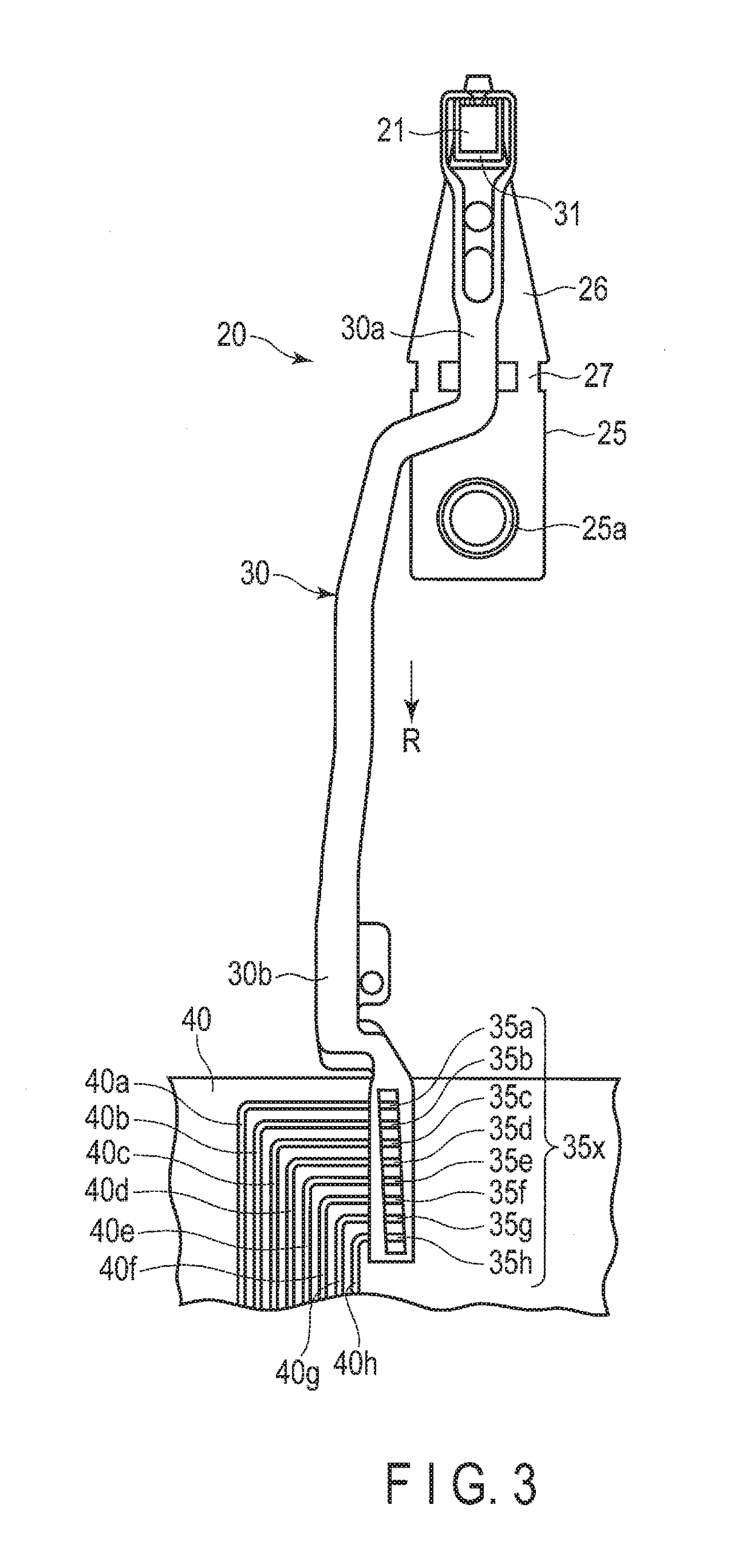
[0054]The flexure body portion 51 includes a proximal portion 51a and a tail portion 51b having structures substantially common to the flexure 30 of the suspension 20 shown in FIG. 3. For example, as shown in FIG. 4, a tail terminal group 55x is formed in the tail portion 51b. An example of the tail terminal group 55x includes a ground tail terminal 55a, sensor tail terminals 55b and 55c, read tail terminals 55d and 55e, a heater tail terminal 55f, and write tail terminals 55g and 55h.

[0055]FIG. 8 is a cross-sectional view of the flexure body portion 51 taken along line F8-F8 of FIG. 4. In FIG. 8, arrow Y indicates a width direction of the flexure body portion 51, and arrow Z indicat...

second embodiment

[0081]FIG. 15 shows a test coupon 52B according to a FIG. 16 is a plan view of a substrate 70 of the test coupon 52B shown in FIG. 15. A pseudo element circuit 105 of the test coupon 52B also includes a main circuit section 100 of a double-layered conductor structure, and an adjusting section 101 of a single-layered conductor structure. The adjusting section 101 comprises a pair of linear conductors 140 and 141 which are shaped like straight lines arranged parallel to each other. The linear conductors 140 and 141 are formed of the second metal (for example, copper) likewise a metal layer 72. The linear conductors 140 and 141 are part of a metal layer 72, and are arranged on a second surface 71b of a dielectric layer 71.

[0082]The linear conductor 140 is formed between an input-side electrical path 92 and an intermediate electrical path 94 which are provided on one side. The linear conductor 141 is formed between an input-side electrical path 93 and an intermediate electrical path 95...

third embodiment

[0084]FIG. 17 is a plan view showing a test coupon 52C according to a FIG. 18 is a plan view of a substrate 70 of the test coupon 52C shown in FIG. 17. A main circuit section 100 of the test coupon 52C comprises second pattern conductors 96 and 97 each having a meandering shape, in other words, which wind in zigzags. The second pattern conductor 96 is connected to an end 82a of a linear conductor 82 via an intermediate electrical path 94 and a connection conductor 112 which are provided on one side. The second pattern conductor 97 is connected to an end 83a of a linear conductor 83 via an intermediate electrical path 95 and a connection conductor 113 which are provided on the other side.

[0085]On the substrate 70 of the test coupon 52C, a first pattern conductor 81 having a meandering shape corresponding to the second pattern conductors 96 and 97 is formed. The first pattern conductor 81 overlaps the second pattern conductors 96 and 97 with a dielectric layer 71 interposed therebetw...


PUM


Abstract

A test coupon includes a pseudo element circuit which is constituted of a main circuit section and an adjusting section. The main circuit section includes a first pattern conductor and second pattern conductors. The first pattern conductor and the second pattern conductors overlap one another with a dielectric layer interposed therebetween. The first pattern conductor electrically conducts to the second pattern conductors. The main circuit section represents the R-component and the L-component of an equivalent circuit, and is a dominant circuit element which determines a signal waveform. The adjusting section includes linear conductors. A peak of a voltage waveform is suppressed by the R- and L-components of the adjusting section.

Description

BACKGROUND OF THE INVENTION1. Field of the Invention[0001]This invention relates to a pseudo flexure for a disk drive comprising a test coupon for use in a test and an evaluation, etc., of an electronic circuit of the disk drive, and a method of testing the electronic circuit for the disk drive.2. Description of the Related Art[0002]A hard disk drive (HDD) is used in an information processing apparatus, such as a personal computer. The hard disk drive comprises a magnetic disk rotatable about a spindle, a carriage turnable about a pivot, etc. On an arm of the carriage, a disk drive suspension (which will be hereinafter simply referred to as a suspension) is provided.[0003]The suspension comprises elements such as a load beam, and a flexure disposed to overlap the load beam. A magnetic head including a slider is mounted on a gimbal portion formed near a distal end of the flexure. The magnetic head is provided with elements for accessing data, that is, for reading or writing data. The...

Claims


Application Information

Patent Timeline
Patent Type & Authority Patents(United States)
IPC IPC(8): G01R31/28
CPCG01R31/2803G01R31/2829G11B5/4846G11B5/486G11B5/455G11B5/484
Inventor SASAKI, FUTAARAI, HAJIMEOKADA, TOMOHISANISHIYAMA, NOBUMASANAGAOKA, KAZUHIRO
Owner NHK SPRING CO LTD
Why Eureka
Try Eureka