X-ray detector

a detector and x-ray technology, applied in the field of x-ray detectors, can solve the problems of increasing reducing the noise at the pixel level, and reducing so as to reduce the noise at the pixel, increase the power consumption of an entire system, and reduce the effect of power consumption

Active Publication Date: 2017-12-12
VIEWORKS
View PDF7 Cites 0 Cited by
  • Summary
  • Abstract
  • Description
  • Claims
  • Application Information

AI Technical Summary

Benefits of technology

[0013]In other words, the typical X-ray detector determines a level of each pixel through a voltage variation of the photodiode induced by X-rays, and in such a case, there is a problem in that a minute discrimination of a pixel level may be difficult due to noise. Also, even though noise at the pixel is reduced, there may be a problem in that the typical X-ray detector is vulnerable to noise generated at post-processing circuits including an ROTC, an ADC, or the like. In addition, power consumed at various post-processing circuits is considerable so that there is a problem in that power consumption of an entire system is increased.
[0014]To address the problems described above, an object of the present disclosure is to provide an X-ray detector being effective against noise and provided with post-processing circuits capable of reducing power consumption, compared with a conventional signal processing method.

Problems solved by technology

In other words, the typical X-ray detector determines a level of each pixel through a voltage variation of the photodiode induced by X-rays, and in such a case, there is a problem in that a minute discrimination of a pixel level may be difficult due to noise.
Also, even though noise at the pixel is reduced, there may be a problem in that the typical X-ray detector is vulnerable to noise generated at post-processing circuits including an ROTC, an ADC, or the like.
In addition, power consumed at various post-processing circuits is considerable so that there is a problem in that power consumption of an entire system is increased.

Method used


Image

  • X-ray detector
  • X-ray detector
  • X-ray detector

Examples


Embodiment Construction

[0024]Hereinafter, one embodiment of an X-ray detector according to the present disclosure will be described with reference to the accompanying drawings. By describing the present disclosure, a thickness of a line, a size of a component and the like, which are shown in the drawings, will be somewhat exaggerated to help clearness of a description and understanding thereof. And, all terms used hereinafter are selected by considering functions in embodiments, and meanings thereof may be different according to a user, the intent of an operator, or custom. Therefore, the meanings of the terms used herein should follow contexts disclosed herein.

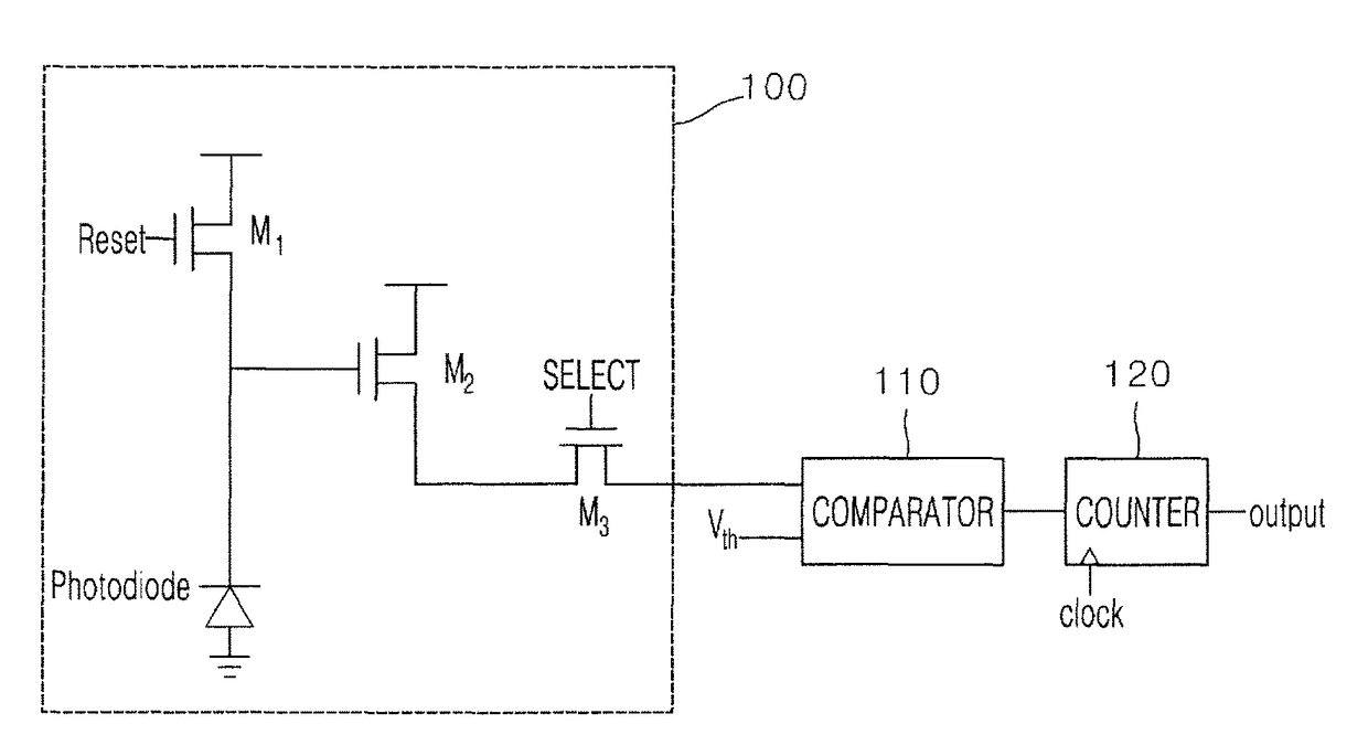
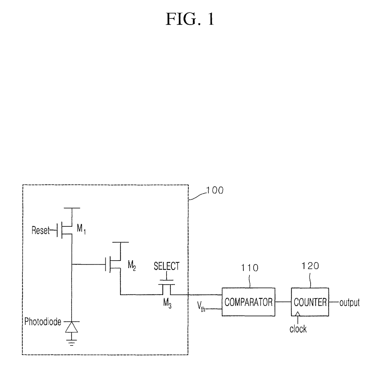
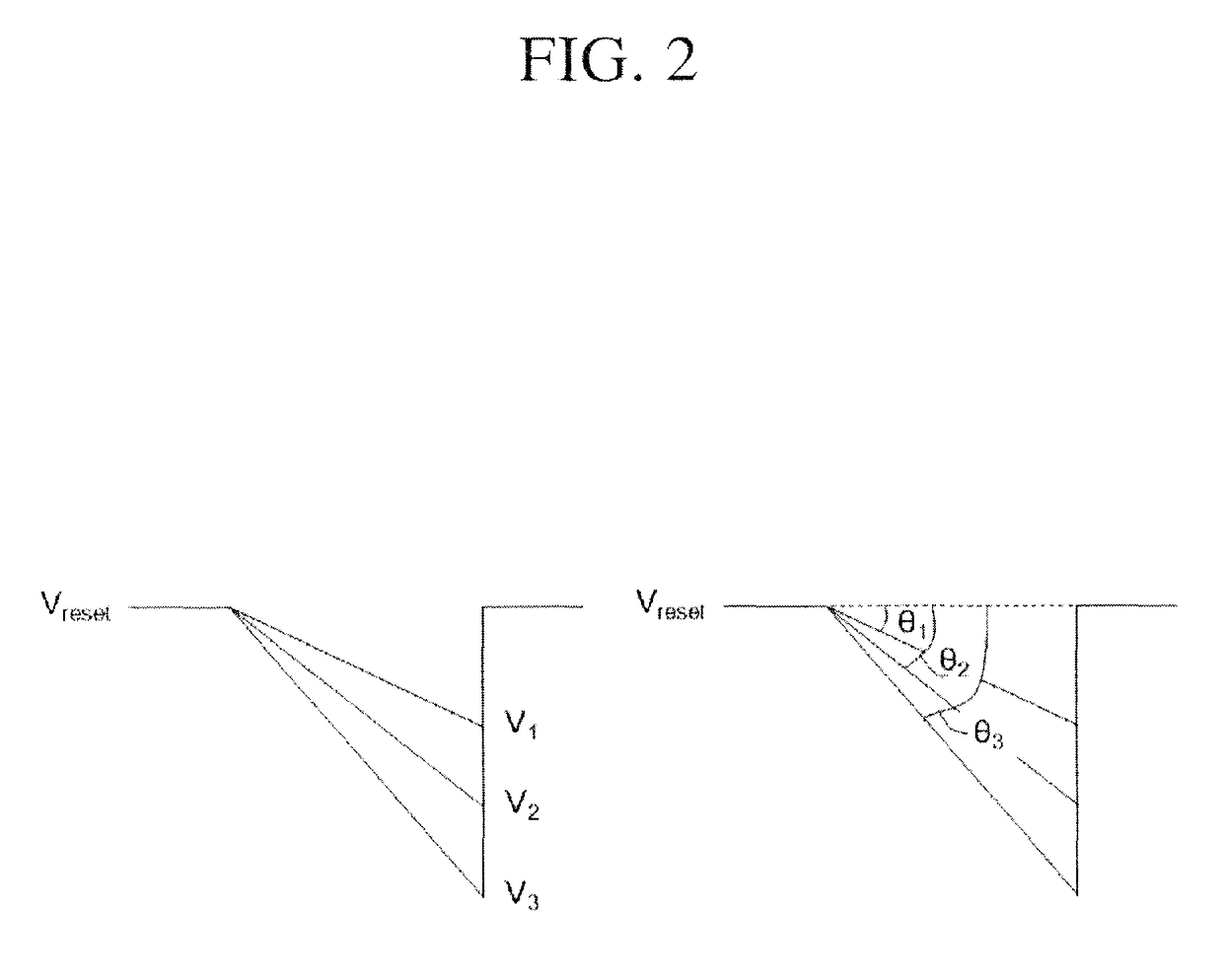
[0025]FIG. 1 is an exemplary diagram illustrating a configuration of an X-ray detector according to one embodiment of the present disclosure, FIG. 2 is an exemplary diagram for describing a voltage output from a pixel unit of the X-ray detector according to one embodiment of the present disclosure, FIG. 3 is an exemplary diagram for describing an X...


PUM


Abstract

The present disclosure relates to an X-ray detector which includes a pixel unit configured to include a photodiode and to output a voltage corresponding to an incident amount of X-rays, a comparator configured to compare the output voltage of the pixel unit with a preset threshold voltage to output a logic signal, and a counter configured to count the output signal of the comparator to convert to a digital output.

Description

CROSS-REFERENCE TO RELATED APPLICATION[0001]This application claims priority under 35 U.S.C. §119 to Korean Patent Application No. 10-2015-0090353, filed Jun. 25, 2015, which is hereby incorporated by reference in its entirety.BACKGROUND[0002]1. Field of the Invention[0003]The present disclosure relates to an X-ray detector, and more particularly, to an X-ray detector for an X-ray signal to output the X-ray signal as a digital signal.[0004]2. Discussion of Related Art[0005]An X-ray detector is a device for detecting an X-ray signal to convert the detected X-ray signal into an electrical signal, and generally converts an X-ray signal into an electrical signal using a photodiode.[0006]In other words, a scintillator or a phosphor being located in front of a photodiode may absorb X-rays to radiate visible light corresponding to the absorbed X-rays, the photodiode may convert the visible light into a photocurrent in proportion to an amount of the visible light, and the converted photocur...

Claims


Application Information

Patent Timeline
Patent Type & Authority Patents(United States)
IPC IPC(8): G01T1/24G01T1/17
CPCG01T1/17G01T1/24
Inventor LEE, BO RAM
Owner VIEWORKS
Why Eureka
Try Eureka