Side folding toolbar for chemical applicator

a toolbar and chemical technology, applied in agricultural machinery, agricultural tools and machines, agriculture, etc., can solve the problems of limited lifting height of the mid-mounted toolbar, increased crop damage and yield loss, and substantial risk

Active Publication Date: 2017-12-19
FAST DISTRIBUTING +1
View PDF27 Cites 7 Cited by
  • Summary
  • Abstract
  • Description
  • Claims
  • Application Information

AI Technical Summary

Benefits of technology

[0013]The rearward folding toolbar includes a laterally rigid mid mounted center toolbar section that is disposed transversely to the direction of travel and allowed to translate vertically through parallel links and corresponding hydraulic actuators pivotally secured to the trailing carriage and the toolbar. A pair of first wing sections extends out from the sides of the center section flanking the center section. These are also known as main wing sections. Each main wing section is suspended from the outer end of the center section by a hinge assembly in the form of a flex hinge. The flex hinges located between the main wings and the center section allow the main wing sections to be pivotally secured to the center section along a vertical axis that enables folding of each main wing rearward into a transport disposition as well as allowing rotation along a horizontal axis for field application in varying land contours.
[0014]A hydraulic cylinder or other actuator operatively secured to the bottom side of the outer end of the center section and the flex hinge assembly is used to rotate each flex hinge assembly to thereby fold each main wing forward into the aligned field position or rearward into the transport position. A latch mechanism and hydraulic cylinder are pivotally pinned to a leading main tube member in the toolbar center section to mechanically secure each side folding main wing parallel to the center section for field operation. The latch mechanism consists of a plate weldment with a radius indentation that rotates vertically on a horizontal axis about the end of the center section by means of a pivotally secured hydraulic cylinder. With each main wing section aligned end to end with the center section in the field position, the radius indentation of each latch assembly is lowered over a cross pin that is secured to the beginning of each leading main wing section tube and axially aligned with the horizontal hinge on each flex hinge assembly. This configuration allows a latch to secure each main wing section in the forward, aligned, field position while still permitting each main wing section to pivot vertically about its horizontal hinge for ground contour following and row end wing tilt capabilities.

Problems solved by technology

Whatever the cause for off-tracking the result is a substantial risk of increased crop damage and yield loss whenever a fertilizer applicator deviates from the center of the crop swath.
However, on mid mounted toolbars the lift height of a mid mounted toolbar is restricted by the height of the carriage hitch.
However, a major problem associated with the conventional vertical folding toolbars is the excessive height of the folded wings in the transport position which thereby increases the possibility of striking overhead obstacles during road transport.
A further problem associated with prior folding toolbars is that during field incorporation they do not have sufficient vertical travel laterally among the toolbar sections to compensate for rolling terrain such as hills, draws, or terraces.

Method used


Image

  • Side folding toolbar for chemical applicator
  • Side folding toolbar for chemical applicator
  • Side folding toolbar for chemical applicator

Examples


Embodiment Construction

[0048]The following description details one or more embodiments to illustrate the principles of the invention. The embodiments are presented as examples but not as limitations as those skilled in the art will recognize that other implements may make use of the principles of the toolbar of the invention and that it may take other forms while remaining within the confines of the inventive concepts. For example, while actuators may be described as hydraulic cylinders, it will be understood that any type of operator that could be used is also contemplated including pneumatic or electric cylinders or rotary actuators in some cases.

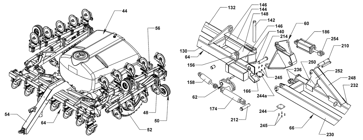
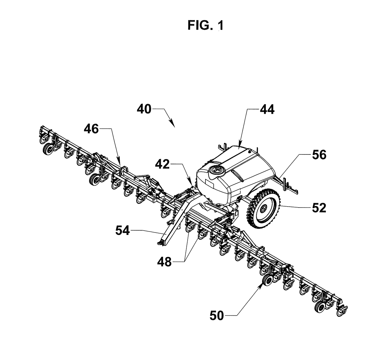
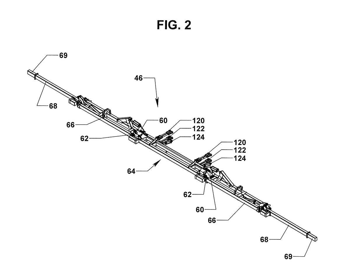
[0049]The present invention provides an improved wide swath toolbar consisting of a center section, flanked by flex hinge mounted side folding main wing sections, and vertical folding outer wing sections. The arrangement advantageously places the center toolbar section in close proximity to the rear wheels of the prime mover and in front of a trailing carriage ...


PUM


Abstract

A multi-row agricultural soil treatment implement includes a semi-trailed carriage and a rearward folding toolbar. The toolbar is suspended from the semi-trailed carriage through parallel links and includes a center section, flex hinges, main wings, main wing latches, and outer flip wings operatively connected to hydraulic cylinders to move them between transport and field position. The main wings fold rearward relative to the center section and are supported by a transport rack but they retain the ability to pivot up or down as needed for ground contour following capability or row end turning.

Description

BACKGROUND OF THE INVENTION[0001]I. Field of the Invention[0002]The present invention relates generally to multi-row, wide-swath, agricultural implements such as chemical applicator implements having a laterally folding toolbar mounted to a towable carriage. More specifically the present invention includes a multi-section toolbar that folds rearward alongside a trailing carriage so as to reduce the overall transport dimensions of the implement.[0003]II. Description of the Prior Art[0004]Agricultural semi-trailed equipment such as, for example, chemical application equipment is used to treat a relatively wide swath of a field in a single pass. A chemical applicator generally consists of a rolling carriage that supports a vessel to carry application material and a toolbar suspended from the carriage framework. The carriage is attached to a prime mover, normally a tractor, through a load bearing pivot point at the rear of the prime mover which allows the tractor-trailer combination to ...

Claims


Application Information

Patent Timeline
Patent Type & Authority Patents(United States)
IPC IPC(8): A01B73/06A01B73/04
CPCA01B73/067A01B73/044
Inventor FAST, VERLYN K.PROHASKA, JAMES B.
Owner FAST DISTRIBUTING
Why Eureka
Try Eureka