Devices and methods for low pressure tumor embolization

a tumor and low-pressure technology, applied in the field of occlusion devices, can solve problems such as toxicity and complications, and achieve the effects of reducing pressure, eliminating reflux, and increasing the number of embolic particles that enter the tumor

Active Publication Date: 2017-12-19
EMBOLX
View PDF135 Cites 29 Cited by
  • Summary
  • Abstract
  • Description
  • Claims
  • Application Information

AI Technical Summary

Benefits of technology

[0022]The occlusion device of the present disclosure causes an immediate pressure drop in the vascular area distal to the occlusion, creating a low pressure zone in the distal artery and surrounding tissue. Since fluid will flow from high pressure to low pressure, blood flow will redistribute in favor of the low pressure zone. When a tumor or other structure with terminal capillary beds is within, or in the vicinity of, the low pressure zone, the blood will flow toward the terminal capillaries since they empty in to veins that have very low pressure. In this instance, the anatomical structure with terminal capillaries acts as a sump that accepts blood flow from surrounding area. By way of example, embolization of tumors in the right lobe of the liver are accessed by a catheter advanced through the right hepatic artery (RHA) and to the vicinity of the tumor. Typically, the catheter tip does not enter the tumor vasculature and remains proximal to the tumor and within the right hepatic artery or branch thereof. In this example, the artery feeding the tumor is typically a branch of the RHA. However, there other distal hepatoenteric arteries that branch from the RHA and flow away from the RHA and to the liver and gastrointestinal tract. In this instance, when using a standard straight catheter, injection of embolic agents from the distal tip of the catheter results in flow of embolic agents into both the tumor and collateral arteries causing antegrade non-target embolization of the liver and gastrointestinal tract, a situation that causes toxicity and complications. The device and method of the present disclosure causes a flow redistribution whereby collateral arteries reverse flow in favor of the tumor, minimizing non-target flow and increasing the number of embolic particles that enter the tumor.
[0023]In some embodiments, the methods and devices disclosed herein include a balloon or other structure that can be expanded or activated to create a full occlusion of the target blood vessel with a concomitant reduction in pressure and flow rate in the anatomical zone distal to the full occlusion that can: (1) eliminate reflux, (2) reduce or eliminate antegrade non-target flow, (3) reduce or eliminate non-target embolization, (4) reduce flow rate and volume moving into the tumor, (5) slow the increase of intra-tumor pressure, (6) slow the onset of blood reflux from the tumor, (7) increase the time that embolic agents can enter the tumor, (8) increase the amount and distribution of embolic agents that are deposited in the tumor, (9) isolate the vascular area distal to the occlusion from the general circulation, (10) create a low pressure zone in the vicinity of the tumor and (11) cause a general inflow of blood toward the low pressure area created by the occlusion.
[0024]In other embodiments, the microcatheter methods and devices disclosed herein, include a balloon or other structure that can be expanded or activated to create a partial occlusion of the target blood vessel such as by creating channels from the proximal end of the occlusion structure to the distal end of the occlusion structure. When in the expanded configuration there is a concomitant reduction in pressure and flow rate in the anatomical zone distal to the occlusion. The device of this embodiment can: (1) provide a distal directed bypass (forward flow) of blood, (2) eliminate reflux, (2) reduce or eliminate antegrade non-target flow, (4) reduce or eliminate non-target embolization, (5) reduce flow rate and volume moving into the tumor, (6) slow the increase of intra-tumor pressure, (7) slow the onset of blood reflux from the tumor, (8) increase the time that embolic agents can enter the tumor, (9) increase the amount and distribution of embolic agents that are deposited in the tumor, (10) isolate the vascular area distal to the occlusion from the general circulation, (11) create a low pressure zone in the vicinity of the tumor and (12) cause a general inflow of blood toward the low pressure area created by the occlusion.
[0028]By isolating the distal arterial space that is adjacent to the tumor from the arterial blood supply, the device of the present disclosure enables pressure measurement to be used to signal a procedural endpoint at a predetermined pressure or pressures. By way of example, the endpoint of the procedure can occur at a point when systolic pressure (120 mmHg) is first reached or at a point when systolic pressure and / or mean arterial pressure is stabilized, however any pressure, pressure profile or algorithm can be used to determine an endpoint of the procedure. Such a measurable endpoint can contribute to standardization of the procedure and improved efficacy.

Problems solved by technology

In this instance, when using a standard straight catheter, injection of embolic agents from the distal tip of the catheter results in flow of embolic agents into both the tumor and collateral arteries causing antegrade non-target embolization of the liver and gastrointestinal tract, a situation that causes toxicity and complications.

Method used


Image

  • Devices and methods for low pressure tumor embolization
  • Devices and methods for low pressure tumor embolization
  • Devices and methods for low pressure tumor embolization

Examples


first embodiment

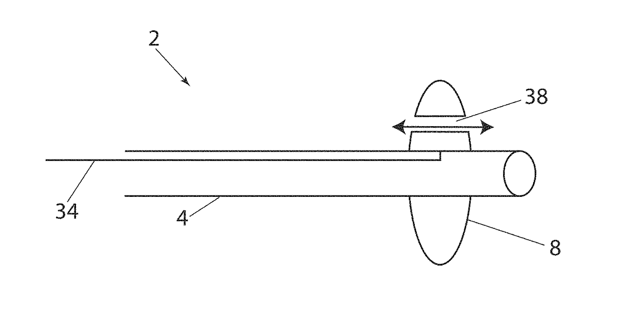
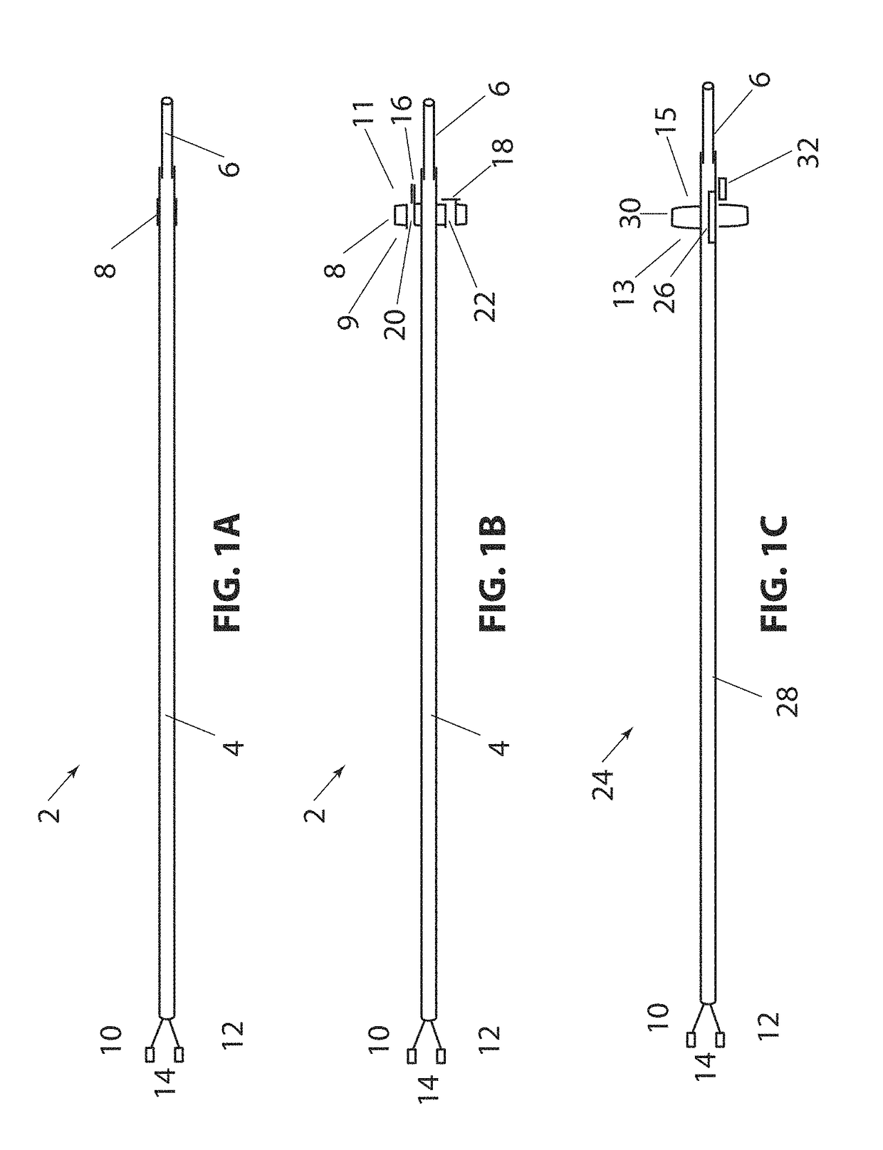
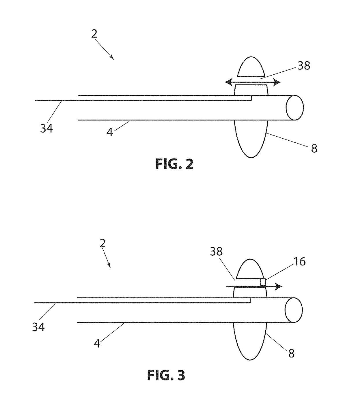
[0127]Referring to FIG. 1B, a longitudinal cross section of the present disclosure is shown, with device 2, balloon 8 (in the expanded configuration) having valve 16 in the open position and valve 18, in the closed position. In this embodiment flow channels 20 and 22 are constructed through balloon 8. Valves 16 and 18 allow fluid to flow in only one direction. Balloon 8 has a proximal side 9 and a distal side 11. By way of example, if fluid pressure is higher on the proximal side of balloon 8 and lower on the distal side of balloon 8, both valves 16&18 will open in response to the pressure difference and allow fluid to flow distally through the valves. If the pressure is higher on the distal side of balloon 8, valves 16 and 18 will close and prevent fluid from flowing proximally. Alternately, the valves can be position or constructed so that fluid can pass proximally and be prevented from flowing in the distal direction. Valves 16 and 18 are shown as a simple “flap” type valve, howe...

embodiment 135

[0158]Referring to FIG. 28A, a distal section of an alternate embodiment 135 of the present disclosure is shown with outer catheter 119, inner catheter 127, nose cone 125, radially constrained balloon 131 and catheter channels 123. The outer catheter 119 is adapted over inner catheter 121, the catheters configured to provide a radially distributed space between inner and outer catheters extending longitudinally along the length of device 135. Outer and inner catheters can have a length of 10 cm to 250 cm, more typically 50 cm to 150 cm and a diameter of between 0.5 Fr and 10 Fr more typically of 1 Fr to 5 Fr. Inner catheter 127 can have a length less than, equal to, or longer than the outer catheter 119, however in the present figure, inner catheter 127 is shown to be longer than outer catheter 119, its distal end forming the catheter extension 127. Nose cone 125 is disposed along the distal extension of inner catheter 127 at some distance from the distal end of outer catheter 119, ...


PUM


Abstract

A method of transarterial embolization agent delivery at a low pressure is provided. The method comprises advancing a delivery device with an occlusion structure in a retracted non-occlusive configuration through a supply artery to a vascular position in the supply artery that is in the vicinity of a target anatomical structure, the target structure having terminal capillary beds, expanding the occlusion structure from the retracted non-occlusive configuration to an expanded occlusive configuration, lowering a mean arterial pressure in a vascular space distal to the expanded occlusion structure, redirecting fluid flow from the collateral vessels toward the lowered pressure vascular space and into the target anatomical structure, injecting an embolization agent through the delivery device and into the lowered pressure vascular space, and delivering the embolization agent from the lowered pressure vascular space into the target anatomical structure. Other catheter assemblies and methods of use are also disclosed.

Description

CROSS REFERENCE TO RELATED APPLICATIONS[0001]This application is a continuation-in-part of U.S. application Ser. No. 14 / 954,699 filed Nov. 30, 2015, which is a divisional of U.S. application Ser. No. 14 / 273,445 filed May 8, 2014, now U.S. Pat. No. 9,205,226, which claims the benefit of U.S. Provisional Application No. 61 / 821,058 filed May 8, 2013, U.S. Provisional Application No. 61 / 915,425 filed Dec. 12, 2013, and U.S. Provisional Application No. 61 / 917,131 filed Dec. 17, 2013, each of which is herein incorporated by reference in its entirety.INCORPORATION BY REFERENCE[0002]All publications and patent applications mentioned in this specification are herein incorporated by reference to the same extent as if each individual publication or patent application was specifically and individually indicated to be incorporated by reference.GOVERNMENT RIGHTS[0003]This invention was made with Government support under Grant No. 1417279 awarded by the National Science Foundation. The Government ...

Claims


Application Information

Patent Timeline
Patent Type & Authority Patents(United States)
IPC IPC(8): A61M31/00A61M25/00A61B17/12A61M25/10A61M5/172
CPCA61B17/12186A61B17/12109A61B17/12136A61M25/0068A61M25/0069A61M25/10A61B17/1204A61M2230/30A61B2017/1205A61M25/1002A61M2005/1726A61M2025/0003A61M2025/0076A61M2025/1052A61M2025/1061A61M2025/1081A61M2025/1093A61M2025/1097A61M2210/1433A61M2210/166
Inventor ALLEN, MICHAEL P.
Owner EMBOLX
Why Eureka
Try Eureka