Taper-faced compression ring and wire therefor

a compression ring and taper-face technology, applied in the field of taper-faced compression ring wires, can solve the problems of large oil consumption and difficulty in obtaining initial uniform surface pressure of piston ring, and achieve the effects of small contact width, improved fuel efficiency, and reduced friction

Active Publication Date: 2017-12-26
RIKEN CO LTD
View PDF15 Cites 5 Cited by
  • Summary
  • Abstract
  • Description
  • Claims
  • Application Information

AI Technical Summary

Benefits of technology

[0006]To solve the above problems, an object of the present invention is to provide a wire for a taper-faced compression ring, which can be provided with an initially conformable surface (contact surface) uniformly and rapidly without increasing a contact width on a peripheral surface, in the production process of the taper-faced compression ring. Another object of the present invention is to provide a long-life taper-faced compression ring having a small contact width, which would not be enlarged even if wearing progressed in response to engine mileage, thereby having reduced friction between an outer peripheral surface of the piston ring and a cylinder liner surface, and thus improved fuel efficiency.DISCLOSURE OF THE INVENTION
[0007]In the present invention, it has been found that when a tapered surface corresponding to the outer peripheral surface of the ring is provided with a second tapered portion, which is then provided with a contact surface, a lapped surface having a predetermined contact width is surely formed, resulting in reduced lapping time.
[0008]In a conventional taper-faced compression ring with no second tapered portion, a small tapering angle (inclination angle θ of a tapered portion) generates large unevenness in contact width even with slight lapping, making it difficult to obtain an initial uniform surface pressure of a piston ring. On the other hand, when the tapering angle θ is large, oil attached to a cylinder wall is scraped when a piston moves upward, resulting in large oil consumption. In that point of view, it was expected before the present invention was made that the formation of a second tapered portion having a large tapering angle θ would extremely increase oil consumption as described above. As a result of intensive research, however, a long-life taper-faced compression ring has been obtained without increasing oil consumption, by setting the outward projection length H of the second tapered portion of a wire to 0.005-0.05 mm, and by setting the radial (outward) projection length H′ of the lapped second tapered portion in a range of 0.001-0.048 mm. Also, lapping can form a contact surface having a predetermined contact width surely and rapidly, thereby suppressing the enlargement of wear width for a long period of time, and thus keeping a predetermined surface pressure.

Problems solved by technology

In a conventional taper-faced compression ring with no second tapered portion, a small tapering angle (inclination angle θ of a tapered portion) generates large unevenness in contact width even with slight lapping, making it difficult to obtain an initial uniform surface pressure of a piston ring.
On the other hand, when the tapering angle θ is large, oil attached to a cylinder wall is scraped when a piston moves upward, resulting in large oil consumption.

Method used


Image

  • Taper-faced compression ring and wire therefor
  • Taper-faced compression ring and wire therefor
  • Taper-faced compression ring and wire therefor

Examples


example 1 (

E1) and Comparative Example 1 (C1)

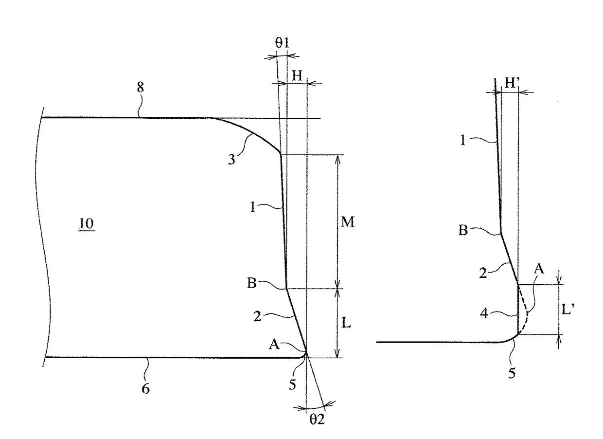
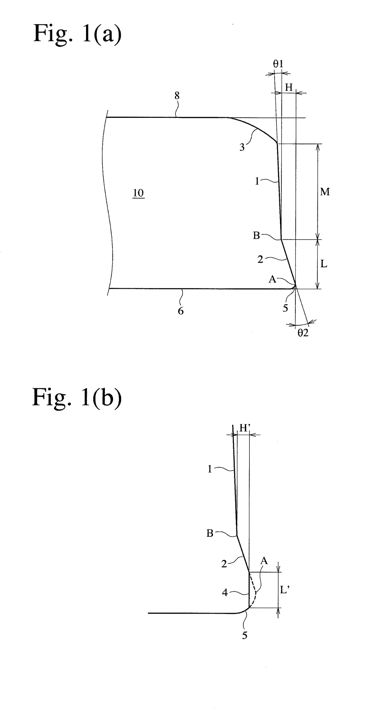
[0025]In Example 1, a steel wire of SWOSC-V according to JIS was formed by rolling and drawing into a wire 10 of about 1 mm in width and about 2.3 mm in thickness for a taper-faced compression ring. The wire 10 had a first tapered portion 1 outward inclined with an inclination angle θ1 of 2.5° and a second tapered portion 2 inclined with an inclination angle θ2 of 5°, which were adjacent to each other on a surface corresponding to the outer peripheral surface of the ring, an outer end of the second tapered portion being located radially outward than an outer end of the first tapered portion by a projection length H of 0.010 mm. A corner 3 of the wire between a surface corresponding to the upper surface of the ring and a surface corresponding to the outer peripheral surface of the ring had a relatively large chamfer, and the second tapered portion 2 had a round lower end portion 5 with R=0.1 mm.

[0026]In Comparative Example 1, the same steel wire as i...

examples 2-18 (

E1-E18) and Comparative Examples 2-5 (C2-C5)

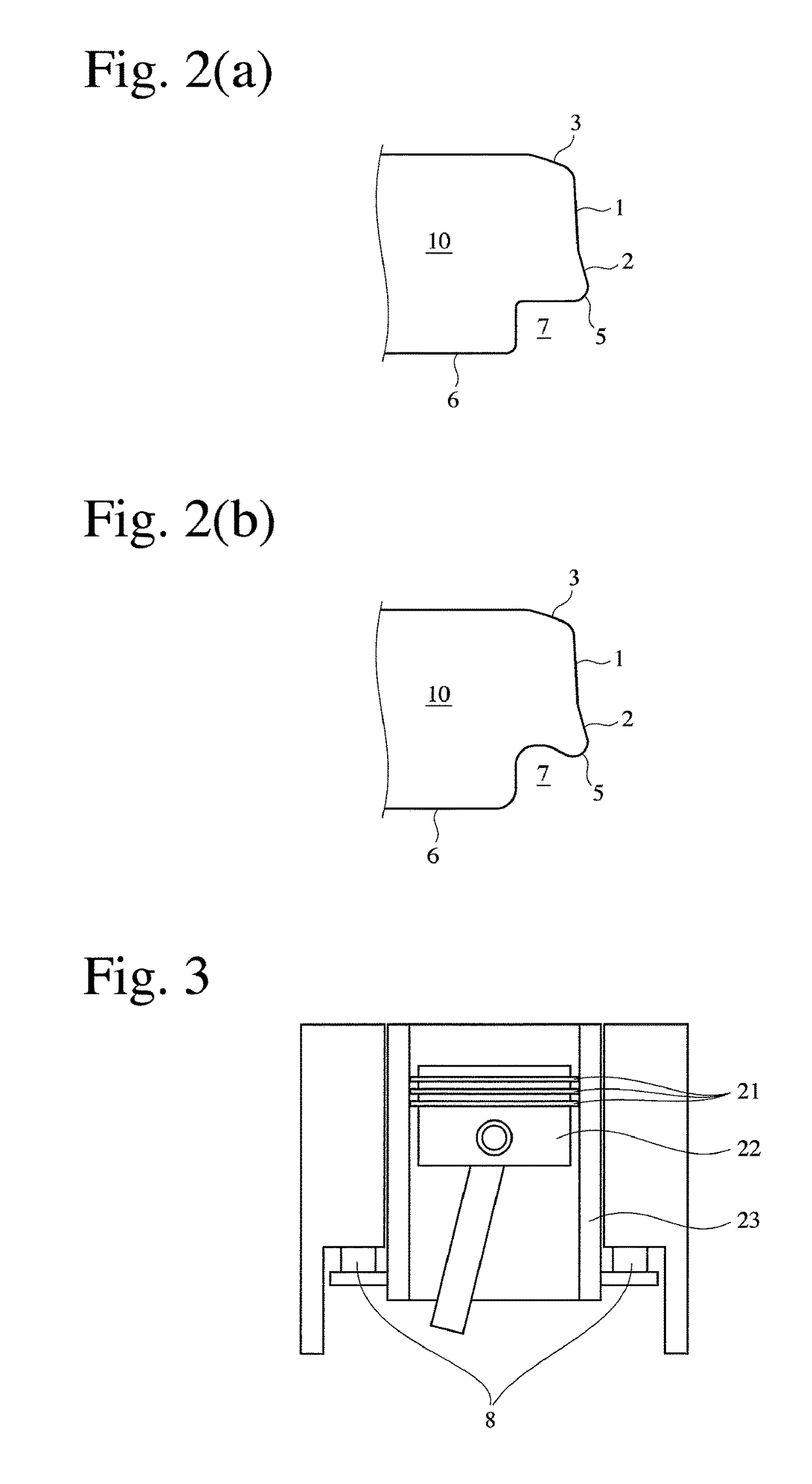
[0037]Wires 10 and taper-faced compression rings 20 were produced in the same manner as in Example 1, except for changing the inclination angles of the first and second tapered portions, and the projection length H of the outer end of the second tapered portion to the outer end of the first tapered portion (and thus the width L of the second tapered portion) as shown in Table 1. Lapping was also conducted in the same manner as in Example 1, to provide the contact width shown in Table 1. The engine test and the friction force measurement test were also conducted in the same manner as in Example 1. The test results are shown in Table 1, together with those of Example 1 and Comparative Example 1.

[0038]

TABLE 1First Tapered Second Tapered PortionPortion θ2 H L H’L’No.θ1 (°)(°)(mm)(mm)(mm)(mm)FMEPLOCE12.550.0100.1140.0060.07463.050.5E22.550.0250.2860.0200.08883.256.1E32.570.0100.0810.0060.06155.843.7E42.570.0200.1630.0140.08370.652.9E52.570.0300...


PUM


Abstract

To provide a wire for a taper-faced compression ring, which can be provided with a running-in surface (contact surface) uniformly and rapidly in the production process of the taper-faced compression ring, a surface of the wire corresponding to an outer peripheral surface of the ring is provided with adjacent outward inclined first and second tapered portions, the inclination angle θ2 of the second tapered portion being larger than the inclination angle θ1 of the first tapered portion, and an outer end of the second tapered portion being located radially outward than an outer end of the first tapered portion by 0.005-0.05 mm. A long-life taper-faced compression ring with reduced friction and improved fuel efficiency is formed by the above wire, the second tapered portion having a lapped surface located radially outward than an outer end of the first tapered portion by 0.001-0.048 mm.

Description

FIELD OF THE INVENTION[0001]The present invention relates to a piston ring used in internal combustion engines, compressed air engines, etc., particularly to a wire for a taper-faced compression ring having a tapered peripheral surface, and a taper-faced compression ring.BACKGROUND OF THE INVENTION[0002]Three to four piston rings are attached to a piston in an internal combustion engine. Two to three upper piston rings are called compression rings, which act not only to keep gas tightness between a combustion chamber and a crank room, but also to dissipate heat from the piston to a cylinder. Also, one to two lower piston rings are called oil rings, which act not only to form an oil film on an inner surface of the cylinder, but also to scrape excessive oil.[0003]Known as a compression ring is a taper-faced piston ring having a tapered peripheral surface, which scrapes an oil attached to an inner wall of a cylinder liner or a cylinder (hereinafter referring to as “inner cylinder wall”...

Claims


Application Information

Patent Timeline
Patent Type & Authority Patents(United States)
IPC IPC(8): B60T11/236F16J9/20F02F5/00
CPCF16J9/20F16J9/206F02F5/00
Inventor WATANABE, MAMORU
Owner RIKEN CO LTD
Why Eureka
Try Eureka