Numerical control device

a control device and numerical technology, applied in the direction of electric programme control, program control, instruments, etc., can solve the problems of extending the machining time, and achieve the effect of improving the accuracy of a particular machining operation and shortening the machining tim

Active Publication Date: 2017-12-26
MITSUBISHI ELECTRIC CORP
View PDF17 Cites 2 Cited by
  • Summary
  • Abstract
  • Description
  • Claims
  • Application Information

AI Technical Summary

Benefits of technology

[0011]According to this invention, acceleration-deceleration data is selected for each movement type and acceleration-deceleration is performed based on the selected acceleration-deceleration data. Thus, shortening of a machining time and improvement of accuracy of a particular machining operation instructed by a fixed cycle or the like can be realized advantageously, without influencing on accuracy and on the like of a usual machining.

Problems solved by technology

As a result, this positioning requires much time and hence results in a cause of elongating a machining time.

Method used


Image

  • Numerical control device
  • Numerical control device
  • Numerical control device

Examples


embodiment 1

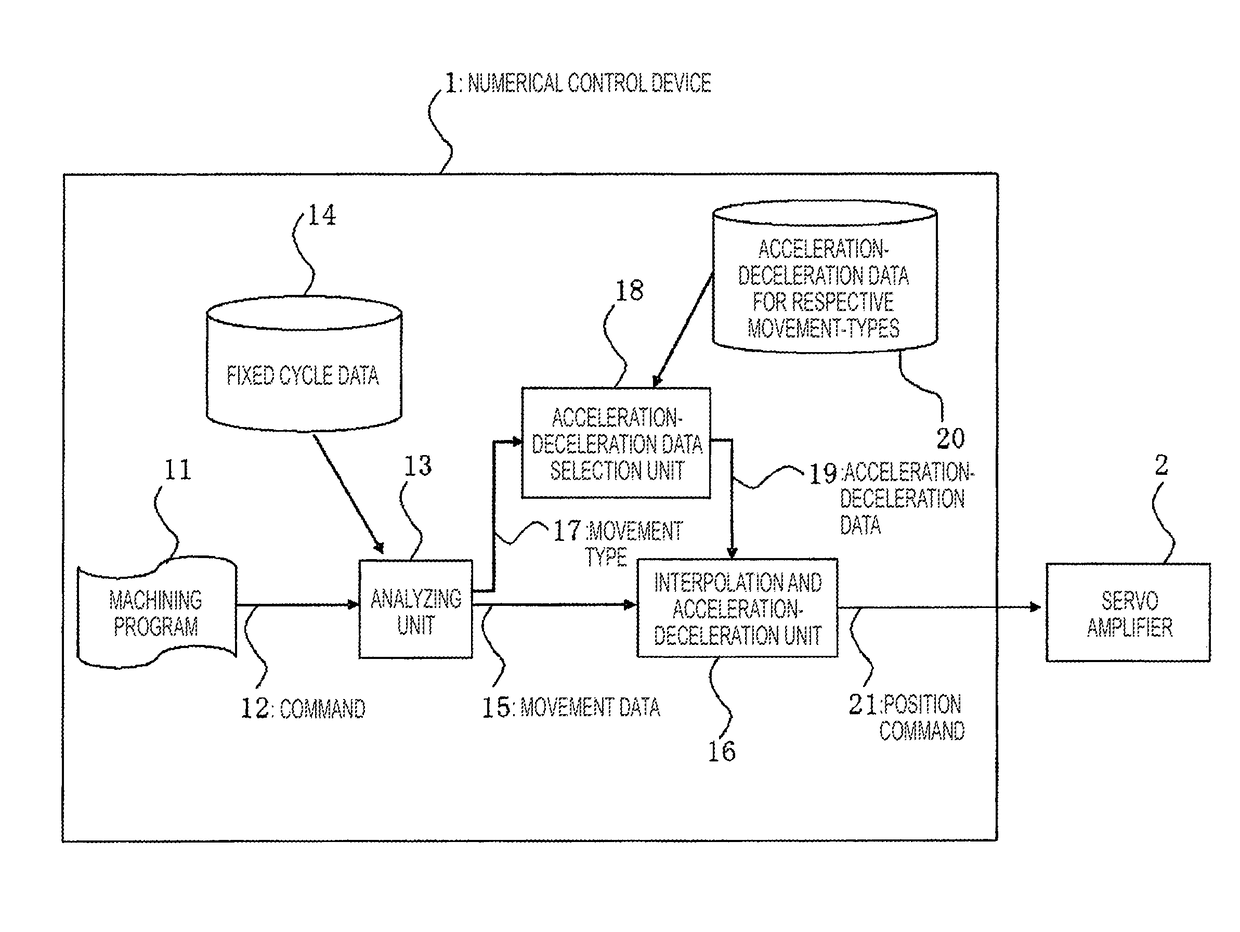
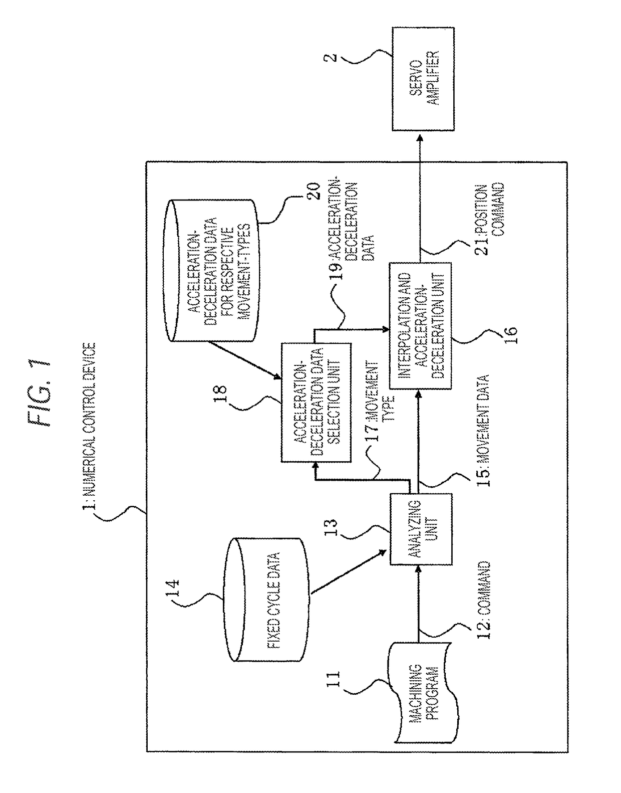
[0022]FIG. 1 is a configuration diagram for explaining the embodiment 1 according to the invention. In the drawing, 1 depicts a numerical control device. 11 depicts machining program, 12 depicts instructions (commands) such as G codes described in the machining program, 13 depicts an analyzing unit, 14 depicts fixed cycle data, 15 depicts movement data 16 depicts an interpolation and acceleration-deceleration unit, 17 depicts a movement type, 18 depicts an acceleration-deceleration data selection unit, 19 depicts acceleration-deceleration data, 20 depicts acceleration-deceleration data for respective movement-types and 21 depicts a position command. The movement data 15 is data defining a movement and is configured of a tool route, a movement speed, a stop time (dwell time), and so on. Interpolation and acceleration-deceleration is performed based on the movement data. The movement type 17 typically represents a type for each fixed cycle for each fixed cycle group.

[0023]The accelera...

embodiment 2

[0041]In the embodiment 1, the description is made as to the example where the acceleration-deceleration method and the acceleration-deceleration parameters and so on are selected for each fixed cycle or fixed cycle group. The embodiment 2 shows an example where the movement type is further subdivided for each movement within the fixed cycle.

[0042]FIG. 6 is a flowchart showing an operation of the acceleration-deceleration data selection unit. In ST1, it is determined whether or not each movement contacts a final shape (final machining shape). The final shape represents a machining shape finally generated in a case of finishing the fixed cycle. For example, in a case of a hole machining cycle using a step feeding where the machining is performed by a plurality of times of cutting feed, it is determined that the cutting feed on the way to a hole does not contact the final shape. In contrast, it is determined that the final cutting feed to the bottom of the hole contacts the final shap...


PUM


Abstract

In a numerical control device 1 which controls positions of respective axes of a machine tool according to a machining program 11, a command 12 instructed to the machining program 11 is analyzed by an analyzing unit 13, thereby obtaining movement data 15 and a movement type 17, an acceleration-deceleration data selection unit 18 selects acceleration-deceleration data 19 according to the movement type 17, and an interpolation and acceleration-deceleration unit 16 generates a position command 21 by performing an interpolation on a movement route, which is instructed to the movement data 15, according to a command speed and performing acceleration-deceleration according to the acceleration-deceleration data 19.

Description

TECHNICAL FIELD[0001]The present invention relates to a numerical control device for controlling operations of a machine tool, and in particular to a numerical control device which performs an acceleration-deceleration control in a particular machining operation instructed by a fixed cycle or the like.BACKGROUND ART[0002]In conventional numerical control devices, a desired machining is realized by combining machining processes accompanying a plurality of movements of a tool. For example, in a case of performing a machining of forming many holes, the machining is performed by combining a positioning process on an X-Y plane, a boring process of lowering along a Z axis, a process of restoring (retracting) to the positioning plane by rising along the Z axis, and so on. In practice, positioning accuracy required in the respective processes differ. However, usually, since an in-position width is the same in each of the processes, the in-position width is unified to an in-position width of...

Claims


Application Information

Patent Timeline
Patent Type & Authority Patents(United States)
IPC IPC(8): G05B19/19G05B19/416
CPCG05B19/19G05B19/416G05B2219/42064
Inventor SATO, TOMONORINISHIWAKI, KENJIHAMAMOTO, SUSUMURYU, MASAKIIUCHI, YUKIHIRO
Owner MITSUBISHI ELECTRIC CORP
Why Eureka
Try Eureka