
Insulation monitoring device

a monitoring device and insulation technology, applied in short-circuit testing, impedence measurement, instruments, etc., can solve the problems of not being able to carry out highly accurate insulation monitoring and exceeding the monitoring level

Active Publication Date: 2018-01-02
FUJI ELECTRIC FA COMPONENTS & SYST CO LTD
View PDF20 Cites 0 Cited by
  • Summary
  • Abstract
  • Description
  • Claims
  • Application Information

AI Technical Summary

Benefits of technology

The invention provides an insulation monitoring device that can accurately monitor insulation based on the load apparatus operating status and ambient temperature. This is achieved by automatically selecting or computing the insulation monitoring setting value, allowing for efficient and effective insulation monitoring.

Problems solved by technology

The private electrical facilities safety management regulation JEAC8021-2006 has 50 [mA] as an upper monitoring limit but, as previously described, the size of the resistance component current differs as a result of the engaging and disengaging of the noise filter 31, and furthermore, the ambient temperature, because of which, when the monitoring setting value compared with the resistance component current is stipulated uniformly and fixedly, there is a problem in that it may happen that the monitoring level is exceeded even when there is no insulation degradation in the electrical circuit and apparatus, and it is not possible to carry out highly accurate insulation monitoring.

Method used


Image

  • Insulation monitoring device
  • Insulation monitoring device
  • Insulation monitoring device

Examples


first embodiment

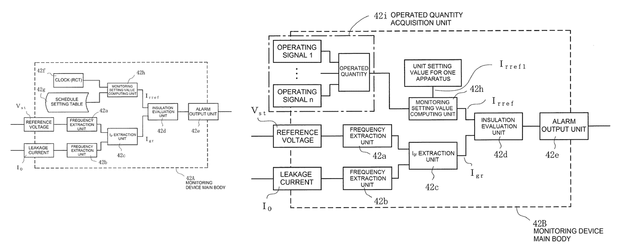
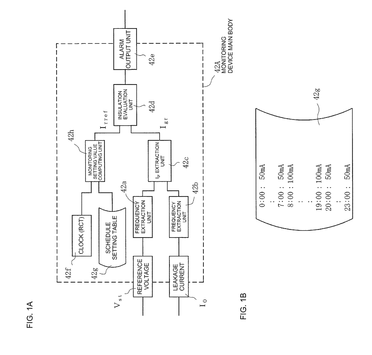
[0043]Firstly, FIG. 1A is a block diagram showing the configuration of a monitoring device main body according to the invention. A monitoring device main body 42A of FIG. 1A is such that, in the same way as in FIG. 13, a frequency component the same as a supervisory signal is extracted from the reference voltage Vst and leakage current IO by the frequency extraction units 42a and 42b. In the Igr extraction unit 42c, resistance component current Igr of the same phase as the reference voltage Vst is extracted from the output of the frequency extraction unit 42b.

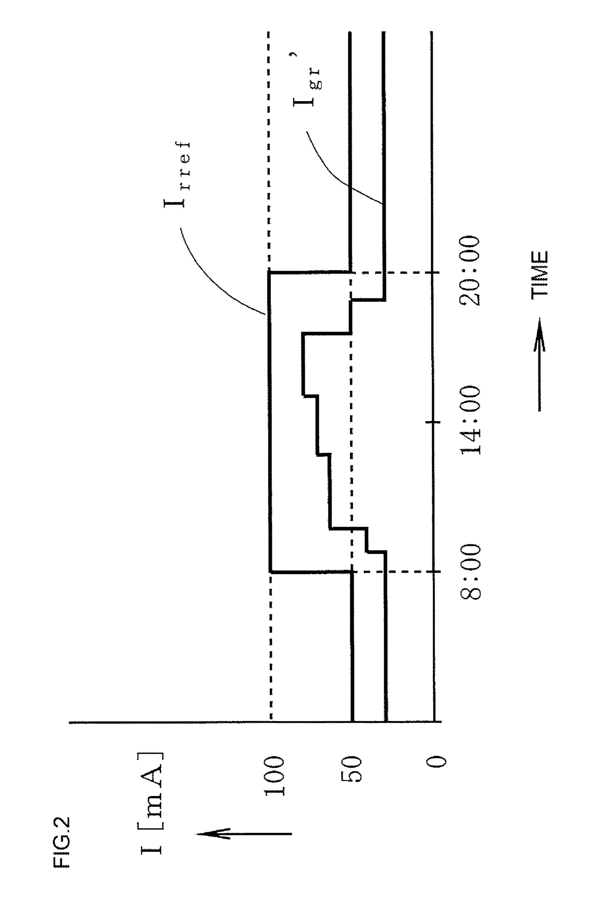
[0044]Meanwhile, monitoring setting values Irref in accordance with a temporal operating schedule (including at least operating time, and also including the quantity operated as necessary) of load apparatus of a system to be monitored are stored in a schedule setting table 42g, as shown in FIG. 1B. That is, when operating an inverter or the like during a one day time span 0:00 to 24:00, a noise filter is connected to the input...

second embodiment

[0050]Next, FIG. 3 is a block diagram showing the configuration of a monitoring device main body according to the invention. A monitoring device main body 42B of FIG. 3 is such that an operated quantity acquisition unit 42i takes in operating signals 1 to n of a quantity n (n is a positive integer of 1 or more) of the load apparatus to which a noise filter is connected when operating as, for example, a Di (digital input) signal, or analog signal of a predetermined level, generated when each apparatus is operating, thereby acquiring the quantity of the load apparatus operated. Also, a monitoring setting value (unit setting value) Irref1 is set for each load apparatus in the monitoring device main body 42B. Herein, the unit setting value Irref1 is a value corresponding to a resistance component error current caused by one load apparatus to which a noise filter is connected when operating.

[0051]The quantity of load apparatus operated output from the operated quantity acquisition unit 4...

fourth embodiment

[0058]FIG. 6 is a block diagram showing the configuration of a monitoring device main body according to the invention.

[0059]A monitoring device main body 42D of FIG. 6 includes an Igc extraction unit 42l as well as the Igr extraction unit 42c. The Igc extraction unit 42l extracts a capacitance component current Igc, which is a frequency component that is the same as the supervisory signal included in the leakage current IO, and whose phase leads by 90 degrees with respect to the reference voltage Vst.

[0060]Furthermore, a monitoring setting value (unit setting value) a for each unit capacitance component current, or a monitoring setting value (unit setting value) β for each unit electrical capacitance converted from the capacitance component current, is stored in the monitoring device main body 42D. FIG. 7 is an illustration of the unit setting value α for each unit capacitance component current, wherein the unit setting value α corresponds to, for example, the resistance component e...


PUM


Abstract

An insulation monitoring device that carries out insulation monitoring of a power system or load apparatus using, for example, an Igr method includes a table in which a monitoring setting value Irref greater than a resistance component error current flowing in accordance with the sum of the electrical capacitance of a capacitor configuring a noise filter on the input side of the load apparatus and the ground insulation capacitance of the power system is set in advance in accordance with an operating schedule of the load apparatus, a monitoring setting value computing unit that outputs the monitoring setting value Irref read from the table in accordance with a current time according to a clock, and an insulation evaluation unit that detects an insulation failure caused by a decrease in ground insulation resistance when a resistance component current extracted by an Igr extraction unit exceeds the monitoring setting value Irref.

Description

CROSS-REFERENCE TO RELATED APPLICATIONS[0001]This application is based on, and claims priority to, International Application No. PCT / JP2013 / 067478, filed on Jun. 26, 2013, the content of which is incorporated herein by reference in its entirety.BACKGROUND[0002]1. Field[0003]The present disclosure relates to an insulation monitoring device that monitors the insulation state of a power system or a load apparatus connected to the power system (hereafter, this will also be referred to collectively as a power system).[0004]2. Description of Related Art[0005]So-called Igr type and IOr type are known as insulation monitoring methods for monitoring the insulation state of a power system, as described in Japanese Patent No. 4,738,274 (e.g., paragraphs [0005] to [0011], FIG. 13, and FIG. 14).[0006]Of these, the Igr type is such that a supervisory signal of a predetermined frequency differing from the system frequency is implanted in the grounding wire of a power receiving transformer, the sup...

Claims


Application Information

Patent Timeline
Patent Type & Authority Patents(United States)
IPC IPC(8): G01R31/02H02H1/00G01R27/18
CPCG01R31/025H02H1/003G01R27/18G01R31/52
Inventor MACHIDA, SATOSHI
Owner FUJI ELECTRIC FA COMPONENTS & SYST CO LTD
Learn More