Positioning insulation plate for cathode bar and anode bar of electrolytic bath

A technology of insulating plates, cathodes and anodes, applied in the direction of electrodes, electrolysis process, electrolysis components, etc., can solve the problems of unfixed spacing between cathode and anode plates, inconvenient maintenance, poor insulation performance, etc., to improve electrolysis production efficiency and reasonable structural design , good insulation performance

Inactive Publication Date: 2015-03-18
TIANHUA INST OF CHEM MACHINERY & AUTOMATION
View PDF6 Cites 0 Cited by
  • Summary
  • Abstract
  • Description
  • Claims
  • Application Information

AI Technical Summary

Problems solved by technology

The material used in this method is expensive to produce, easy to age, and has a short service life; the second method is to put an insulating glue on the end of the cathode and anode rods.
For the second method, due to the need for manual work, the labor intensity is high, the replacement cost is high, and the insulating glue is easily damaged, which makes maintenance inconvenient, and the insulation performance is poor, which can easily cause a short circuit in the electrolytic cell.
Moreover, these two methods do not have a specific positioning device, and only rely on the gravity of the cathode and anode rods of the electrolytic cell to achieve their fixation on the conductive bus, so that the positioning performance of the cathode and anode rods is poor, the distance between the cathode and anode plates is not fixed, and the electrolysis process is stable. Poor performance, high energy consumption, low production efficiency

Method used


Image

  • Positioning insulation plate for cathode bar and anode bar of electrolytic bath
  • Positioning insulation plate for cathode bar and anode bar of electrolytic bath

Examples


Embodiment Construction

[0011] The present invention will be described in further detail below in conjunction with the accompanying drawings. It should be understood that the following examples are only used to illustrate the present invention but not to limit the scope of the present invention.

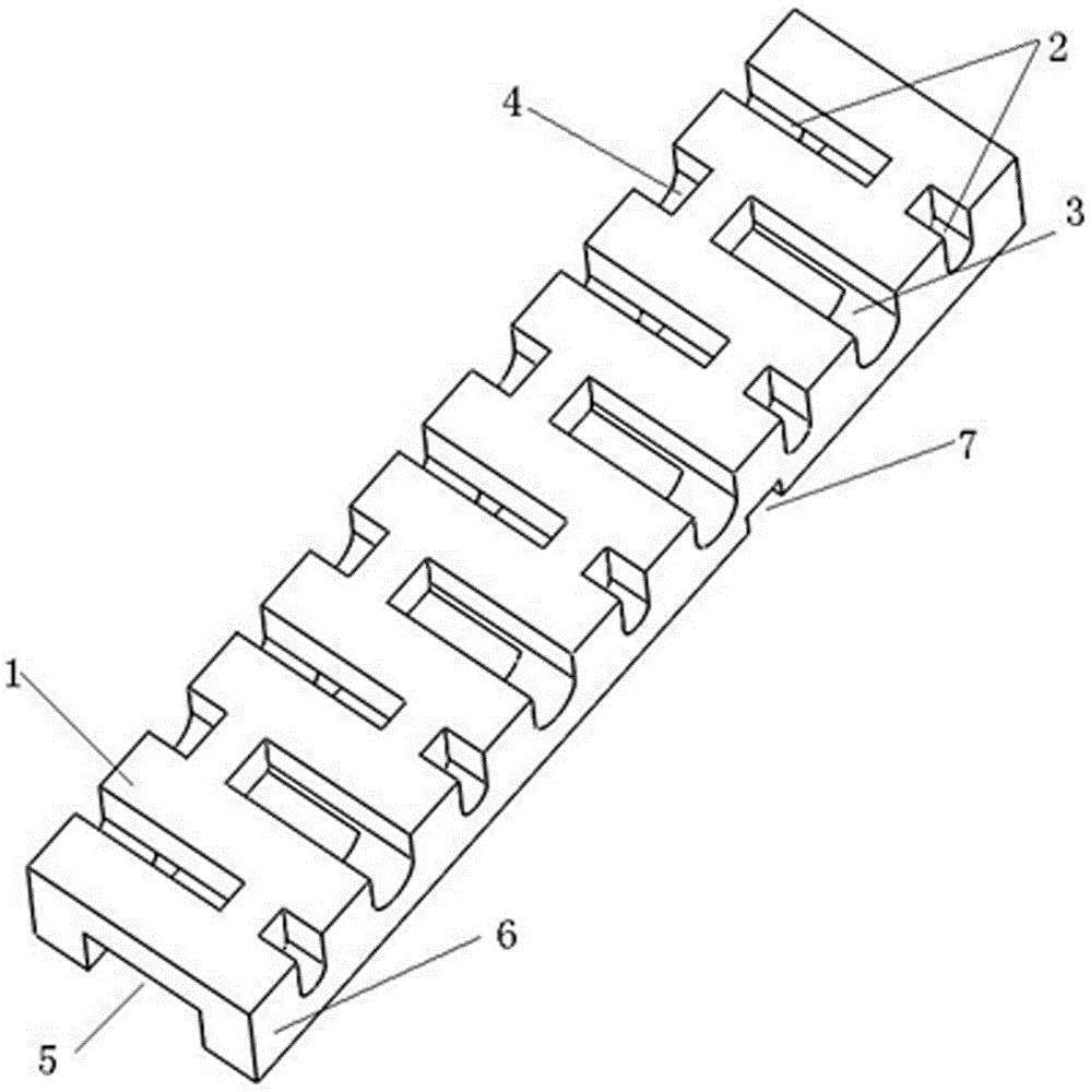
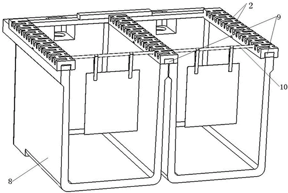
[0012] Such as figure 1 , figure 2 As shown, an electrolytic cell cathode and anode rod positioning insulation plate, the upper surface 1 of the positioning insulation plate is arranged with a plurality of rows of cathode and anode rod positioning grooves 2, the distance between the positioning grooves 2 is determined by the distance between the cathode and anode plates and its The size is determined by the size of the cathode and anode rods required for electrolysis. The positioning groove 2 is composed of long and short grooves 3 and 4 that are not connected to each other; two adjacent rows of long and short grooves 3 and 4 are arranged opposite to each other. The lower surface of the positioning insu...


PUM


Abstract

The invention discloses a positioning insulation plate for a cathode bar and an anode bar of an electrolytic bath. A plurality of rows of cathode and anode bar positioning grooves are arranged on the upper surface of the positioning insulation plate, and the positioning grooves consist of long grooves and short grooves, which are not communicated with each other; the long grooves and the short grooves in two adjacent rows are arranged in a face-to-face way, and the lower surface of the positioning insulation plate is provided with a cavity, the cavity is communicated with the long groove, and the lower bottom surface of a side wall of the positioning insulation plate is provided with a discharging hole. The positioning insulation plate is formed by integrally pouring vinyl-based resin concrete. The positioning insulation plate has advantages of reasonable structure design, good positioning performance, good insulating property, convenience and easiness in installation, high strength, long service life and the like.

Description

technical field [0001] The invention belongs to the technical field of manufacturing in the nonferrous metal hydrometallurgy industry, and in particular relates to a positioning insulating plate for cathode and anode rods of an electrolytic cell. Background technique [0002] In the electrolytic workshop, the electrolytic cells are arranged horizontally, and conductive busbars are respectively placed on the two side walls. Adjacent side walls of two adjacent electrolytic cells share a conductive bus bar, and the cathode and anode rods rest on the conductive bus bar. In order to ensure the good stability of the electrolysis process, on the one hand, on the conductive bus on one side of the electrolytic cell, the connection state of the cathode and anode rods must be opposite to that of the conductive bus, that is, if the anode rod is connected to the conductive bus, the cathode rod is insulated from the conductive bus, and The connection status of the two ends of the same ro...

Claims


Application Information

Patent Timeline
Patent Type & Authority Patents(China)
IPC IPC(8): C25C7/02
Inventor 刘继向刘世青吴生贵钱海林宋丽芸李云海
Owner TIANHUA INST OF CHEM MACHINERY & AUTOMATION
Why Eureka
Try Eureka