
Method and apparatus for neutron detection

a technology of neutron detection and method, applied in the direction of instruments, radiation measurement, measurement devices, etc., can solve the problem of restricting the use of neutrons in many applications

Active Publication Date: 2018-01-02
UK RES & INNOVATION LTD
View PDF22 Cites 1 Cited by
  • Summary
  • Abstract
  • Description
  • Claims
  • Application Information

AI Technical Summary

Benefits of technology

Enables the determination of neutron spectra in a physically small and lightweight system, improving the characterization of neutron fields with enhanced energy resolution and sensitivity, particularly for fast and thermal neutrons.

Problems solved by technology

However, BSSs are large and heavy, which restricts their usage in many applications.

Method used


Image

  • Method and apparatus for neutron detection
  • Method and apparatus for neutron detection
  • Method and apparatus for neutron detection

Examples


first embodiment

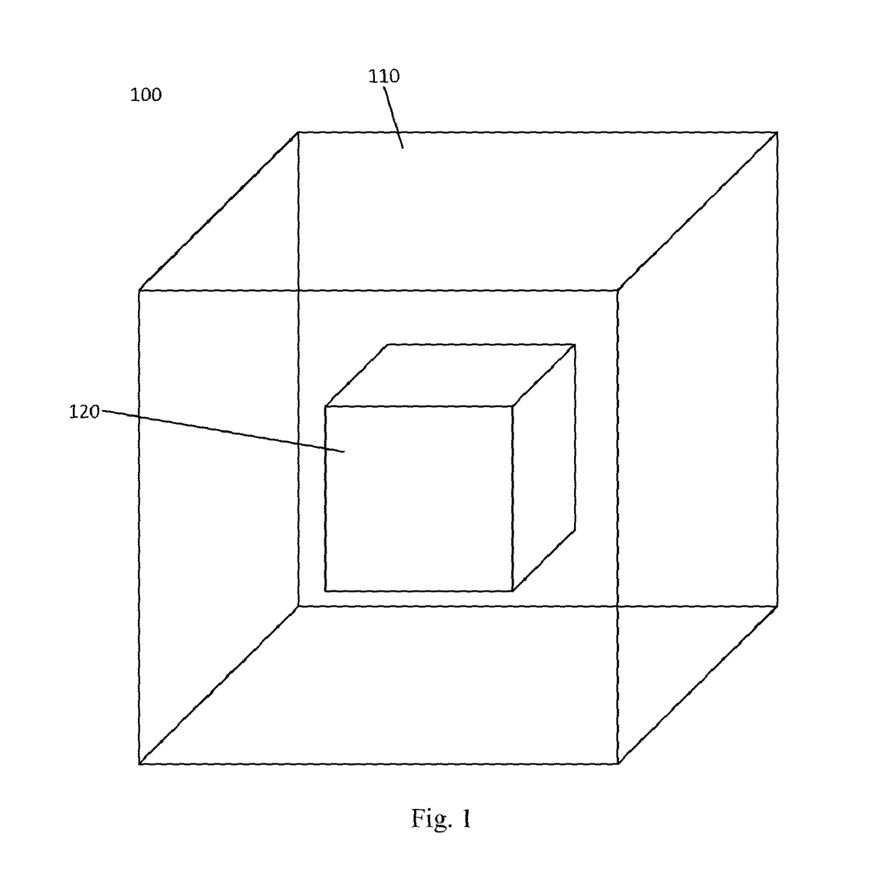
[0018]FIG. 1 illustrates a neutron detector 100 according to the invention. The neutron detector 100 is suitable for neutron spectrometry wherein an energy spectrum is determined of a neutron field to which the detector 100 is exposed. In particular, the detector 100 is suitable for determining the spectrum of a neutron field. The neutron field may include a fast neutron component, wherein the fast neutron component has an energy above 1 MeV.

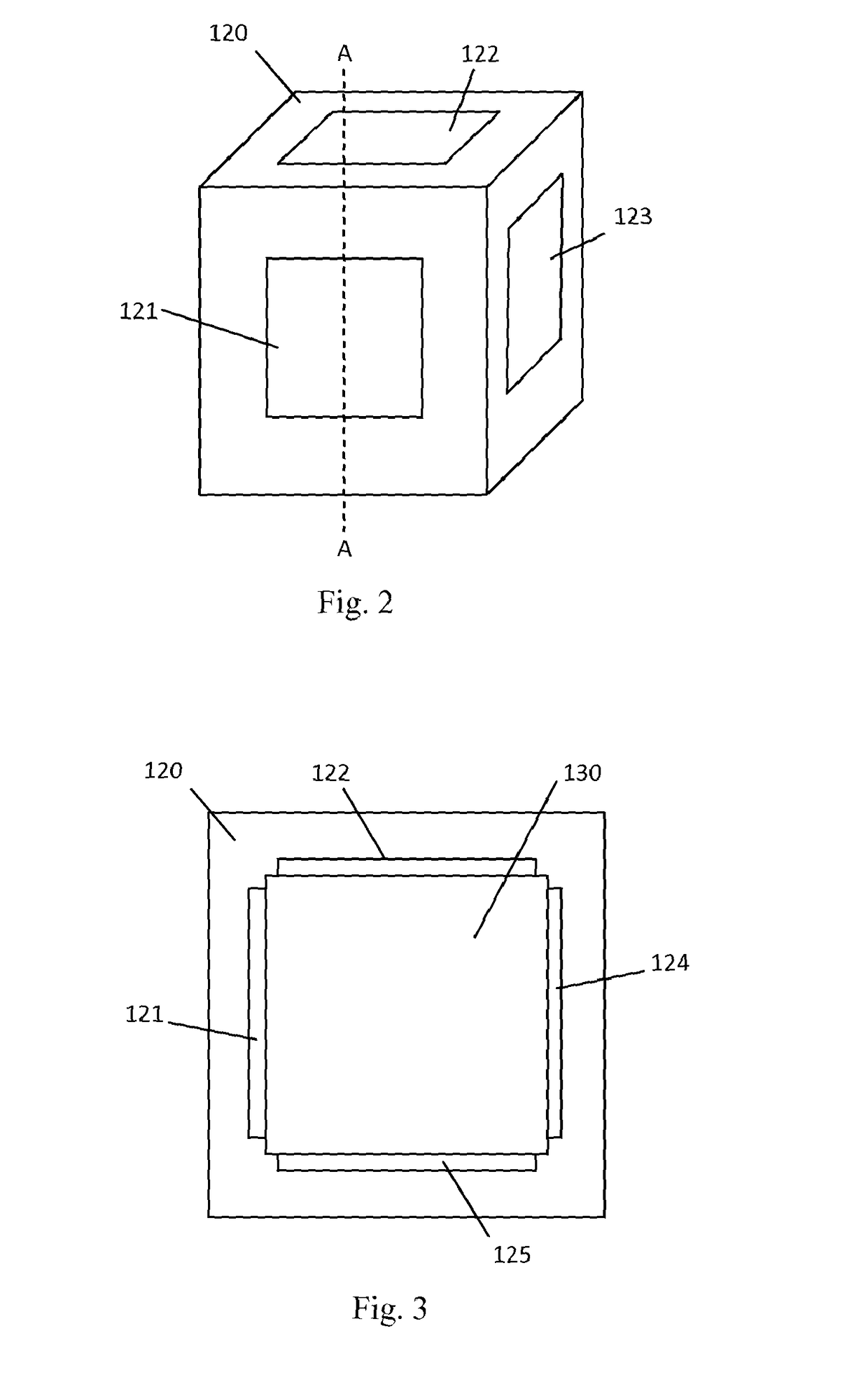
[0019]FIG. 1 is an illustration of the detector 100, whilst FIGS. 2 and 3 only illustrate a semiconductor portion 120 of the detector 100. FIG. 3 is a cross-section along line A-A of the semiconductor portion shown in FIG. 2. It will be appreciated that the Figures are not drawn to scale. FIG. 4 is a schematic illustration of a system according to an embodiment of the invention.

[0020]The neutron detector 100 comprises a convertor 110 which is arranged to encase a semiconductor based detector 120. In the embodiments shown in FIG. 1, the convertor...

second embodiment

[0025]In embodiments of the invention the detector 120 is formed from detector portions 121-126 having sensitive volumes arranged in at least two axes or orientations. For example detector portions 121, 122 are arranged in axes which intersect at an angle of substantially 90°. Similarly, the invention is shaped as a tetrahedron, as will be explained, wherein detector portions are arranged in axes which intersect at around 70°. Other shaped embodiments are also envisaged. The orientation of each detector portion 121-126 may be defined by a normal vector of a substrate of the detector portion 121-126 or of a surface of the sensitive region. Embodiments of the invention include non-parallel arrangements of detectors. In other words, where the normal vectors of each detector portion 121-126 intersect. The arrangement of detectors in at least two orientations improves a likelihood of the detector 120 distinguishing between as many ionising particles resulting from an interaction of a neu...


PUM


Abstract

Embodiments of the present invention provide a neutron spectrometry system, comprising a plurality of semiconductor detector portions arranged in close proximity, wherein the detector portions are arranged in at least two non-parallel axes, wherein each detector portion is arranged to output a detection signal indicative of energy deposited in the detector portion by ionising particles induced in the device by incident neutrons, and a control unit arranged to receive the plurality of detection signals, and to allocate detection signals to one or more of a plurality of channels based on a number of substantially coincident detection signals for determining a spectrum of incident neutrons based thereon.

Description

CROSS-REFERENCE TO RELATED APPLICATIONS[0001]This application is a U.S. national counterpart application of International Application Serial No. PCT / GB2012 / 051739, filed Jul. 20, 2012, which claims priority to Great Britain Patent Application No. 1112457.5, filed Jul. 20, 2011. The entire disclosures of both of the foregoing applications are hereby incorporated by reference.BACKGROUND[0002]Neutrons are neutral particles which are not directly detectable electronically. Spectral information of neutron fields is often desired to be characterised, such as by surveying the neutron radiation environment at flight altitudes or in nuclear facilities. To measure a neutron spectrum Bonner sphere spectrometers are often used. A Bonner sphere spectrometer (BSS) comprises a plurality of spherical detectors, often six to fourteen, each of which includes a thermal neutron detector surrounded by a moderator of various thicknesses. The thickness of the moderator provides each detector with a differ...

Claims


Application Information

Patent Timeline
Patent Type & Authority Patents(United States)
IPC IPC(8): G01T3/08G01T3/00
CPCG01T3/085G01T3/08G01T3/003G01T3/001
Inventor PLATT, SIMON PHILIPCAI, XIAO XIAO
Owner UK RES & INNOVATION LTD
Learn More