

Bar code reader including linear sensor array and hybrid camera and bar code reader
a bar code reader and sensor array technology, applied in the field of imaging modules, can solve the problems of utilizing complex objective lens assemblies originally designed for relatively, and limiting the versatility and working range of the system
- Summary
- Abstract
- Description
- Claims
- Application Information
AI Technical Summary
Benefits of technology
Problems solved by technology
Method used
Image

Examples
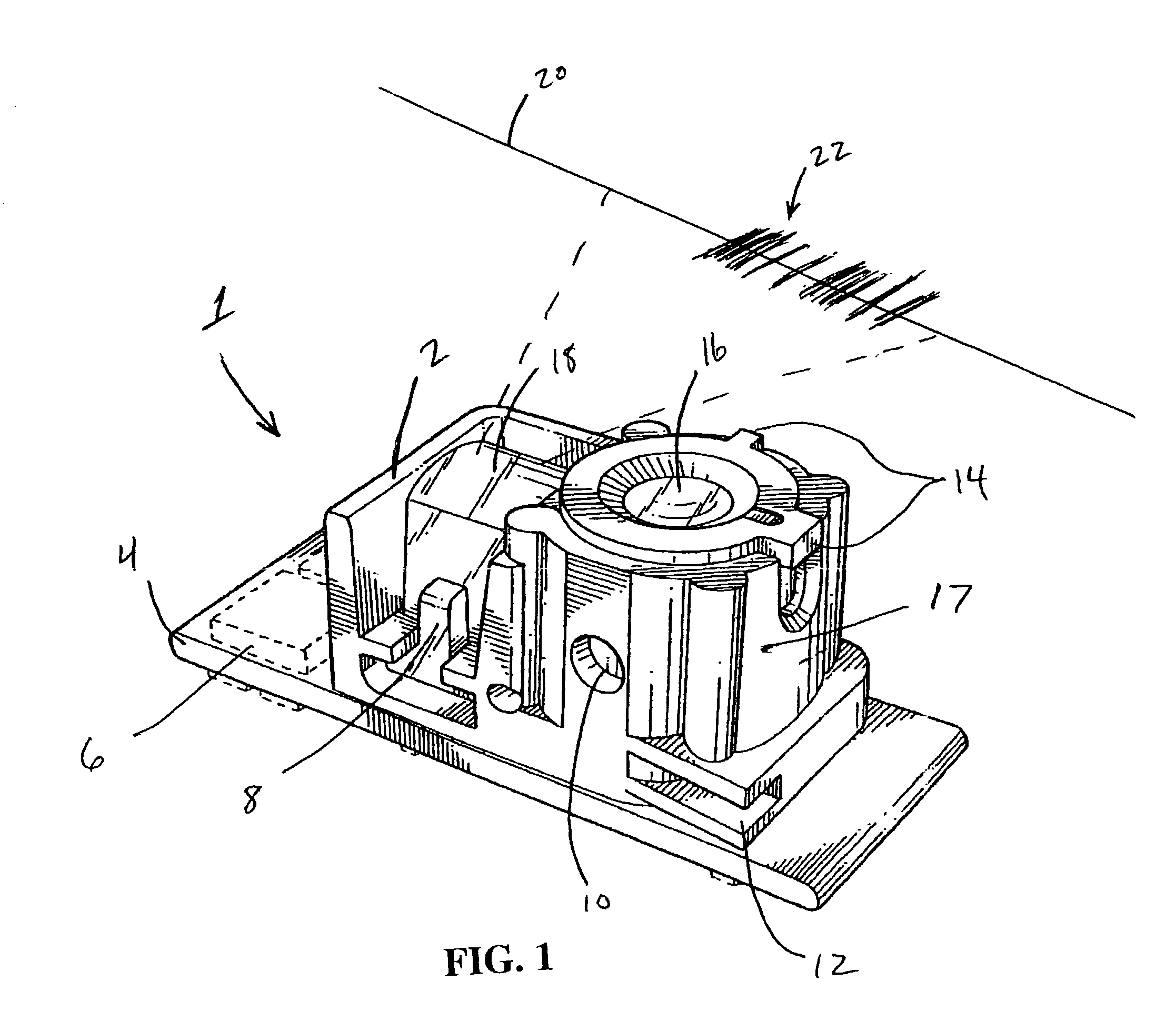
first embodiment
Extended Depth of Focus, First Embodiment
[0067]In accordance with an alternative embodiment, the working range of the bar code reader device 1 may be increased by provided multiple linear rows 704a–704i, each being preferably the same as the preferred linear array 704 described above with reference to FIG. 3, and positioning the rows 704a–704i as a plane of the image sensor 510 at an angle which is not perpendicular to the optical axis of the focusing lens. FIG. 6 illustrates how a bar code reader can operate with an increased working range. Specifically, an image sensor 510 and a focusing lens 520 are relatively oriented as shown schematically at FIG. 6. The image sensor 510 comprises a plurality of horizontal rows of pixels 704a–704i facing the lens 520. As mentioned, each row of pixels is preferably the same as or similar to the preferred single linear array 704 described above with reference to FIG. 3. Although not illustrated in FIG. 6, it will be recognized that the device ill...
second embodiment
Extended Depth of Focus, Second Embodiment
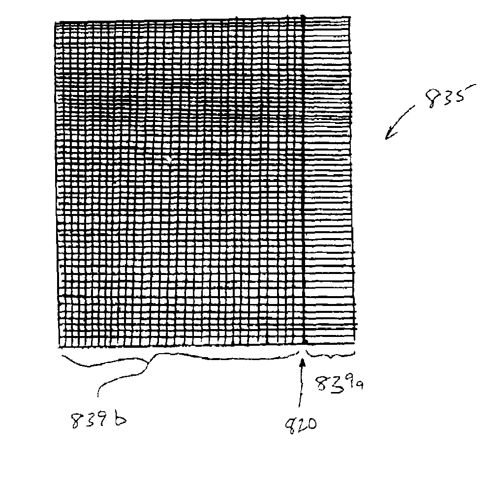
[0069]FIG. 7 schematically illustrates a dual linear image scanner or 1-D bar code reader according to an alternative embodiment including multiple optical paths for focusing bar code images from various distances from the bar code reader optics. Either of the 1-D bar code reader system 1 of FIGS. 1 and 3 or the hybrid system 800 of FIG. 9A (see below) may be modified to include the features of FIG. 7. Generally, a pair of lenses 916a and 916b are used, wherein each of the lenses 916a and 916b is the same or similar to the lens 16 of FIG. 1, except that each has a different working range for resolving 1-D bar code symbols on their respective sensors 920a and 920b. Using the multiplexer electronics described below with reference to FIG. 8, each sensor is sampled for a resolvable bar code symbol, thus enhancing the effective working range of the overall system over a system including only one lens 16. As with the hybrid system of FIG. 9A, the ...
PUM
 Abstract
Description
Claims
Application Information