
Radiation detection apparatus and radiological imaging apparatus

a detection apparatus and radiological imaging technology, applied in the direction of x/gamma/cosmic radiation measurement, radioation controlled devices, instruments, etc., can solve the problems of low sensitivity of the scintillator, inability to resolve the entry of scattered radiation, and degraded images, so as to improve the sensitivity and thus detection accuracy, increase the arrangement density of semiconductor radiation detection elements, and improve the effect of sensitivity

Active Publication Date: 2007-04-10
HITACHI LTD
View PDF4 Cites 17 Cited by
  • Summary
  • Abstract
  • Description
  • Claims
  • Application Information

AI Technical Summary

Benefits of technology

The present invention provides a radiation detection apparatus that can improve the arrangement density of semiconductor radiation detection elements and can be replaced with a new one as required. The apparatus includes a detector holding member in which a plurality of semiconductor radiation detection elements are arranged in a matrix and a coupling member that releasably mount a detector unit holding member. The apparatus also includes a positioning device in a part of the detector unit holding member in which no second connector portions are located. The arrangement density of semiconductor radiation detection elements is improved, and each detector holding member can be easily replaced. The radiological imaging apparatus includes a radiation detection section in which the semiconductor radiation detection elements are arranged opposite an emission source of radiation. The sensitivity is improved, and the detection accuracy is increased. The effective sensitivity is improved to reduce the time required for image pickup.

Problems solved by technology

Consequently, the scintillator disadvantageously has a low energy resolution and cannot resolve entering scattered radiation.
Accordingly, problems with the scintillator include degraded images or an increase in the time required for imaging.
However, they also have a problem attributed to the S / N ratio.

Method used


Image

  • Radiation detection apparatus and radiological imaging apparatus
  • Radiation detection apparatus and radiological imaging apparatus
  • Radiation detection apparatus and radiological imaging apparatus

Examples


Embodiment Construction

[0024]Now, with reference to the drawings as required, a detailed description will be given of preferred embodiments of a radiation detection apparatus according to the present invention and a radiological imaging apparatus using the radiation detection apparatus. In the description below, description will be given of the embodiments as well as a semiconductor radiation detector, an integrated circuit, and the like.

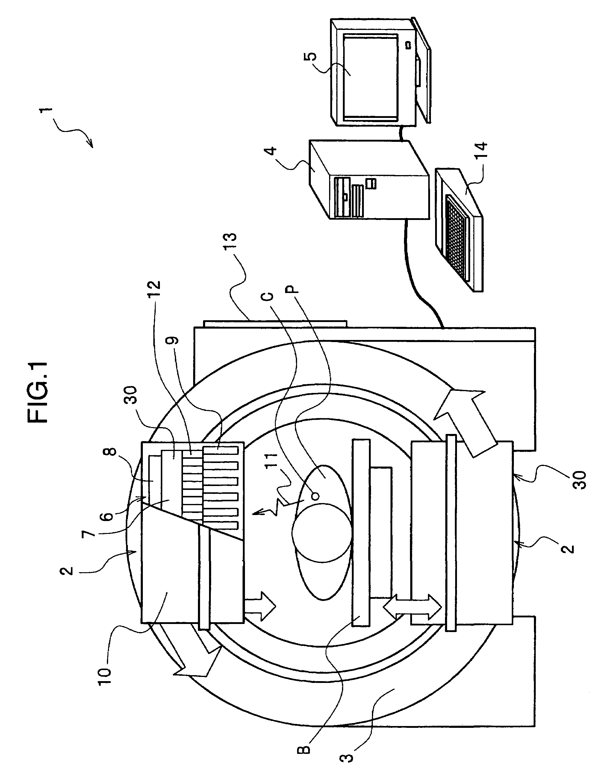
[0025]With reference to FIG. 1, description will be given of a SPECT (Single Photon Emission Computer Tomography) Apparatus 1 according to an embodiment of a radiological imaging apparatus according to the present invention.

[0026]The SPECT apparatus 1 comprises a pair of radiation detection apparatuses 2, 2, a rotating support member 3, a data collection and analysis device 4, and a display device 5. The radiation detection apparatuses 2, 2 are installed on the rotating support member (rotating device) 3 at different positions separated by 180 or 90°. Each of the radiatio...


PUM


Abstract

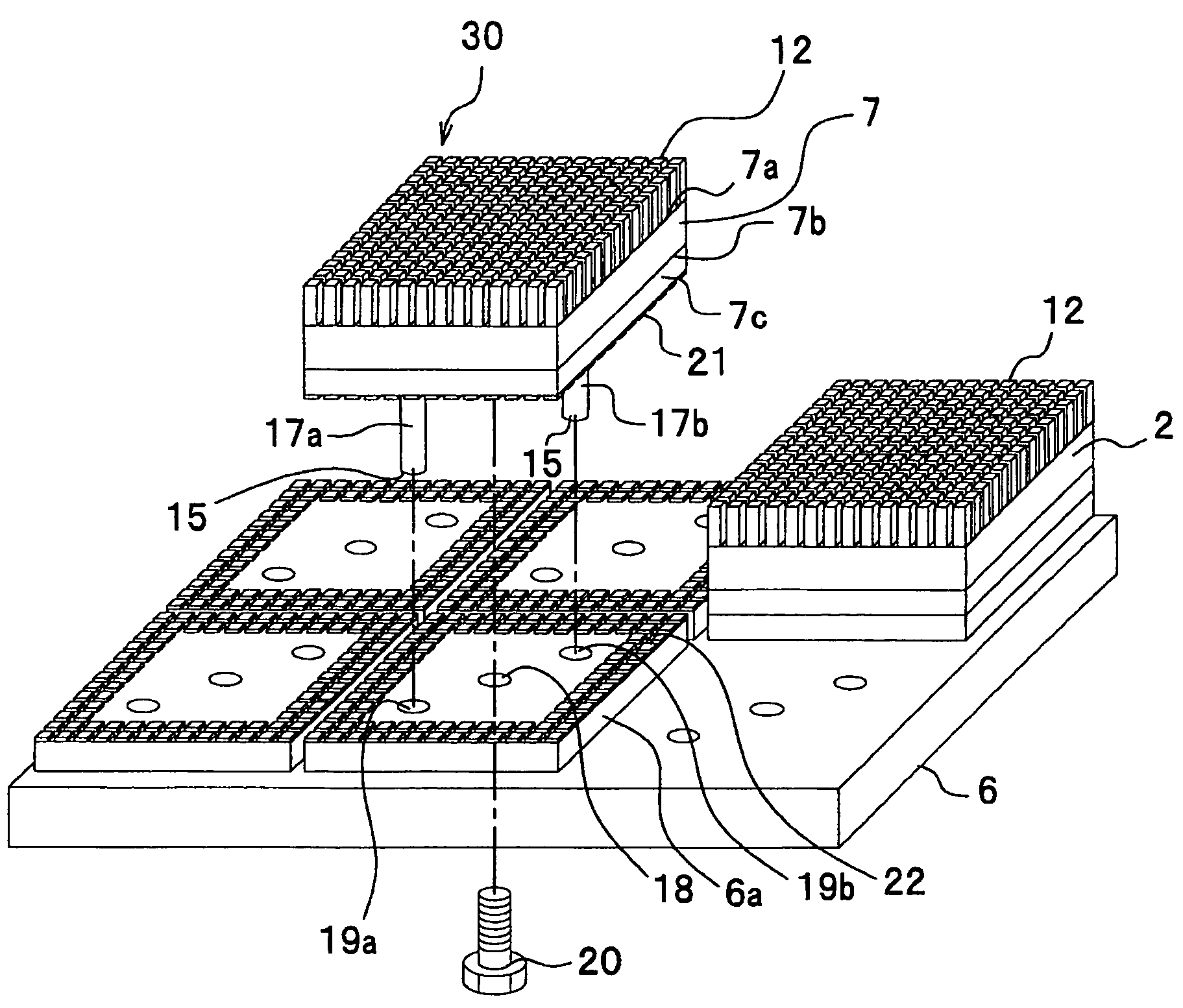
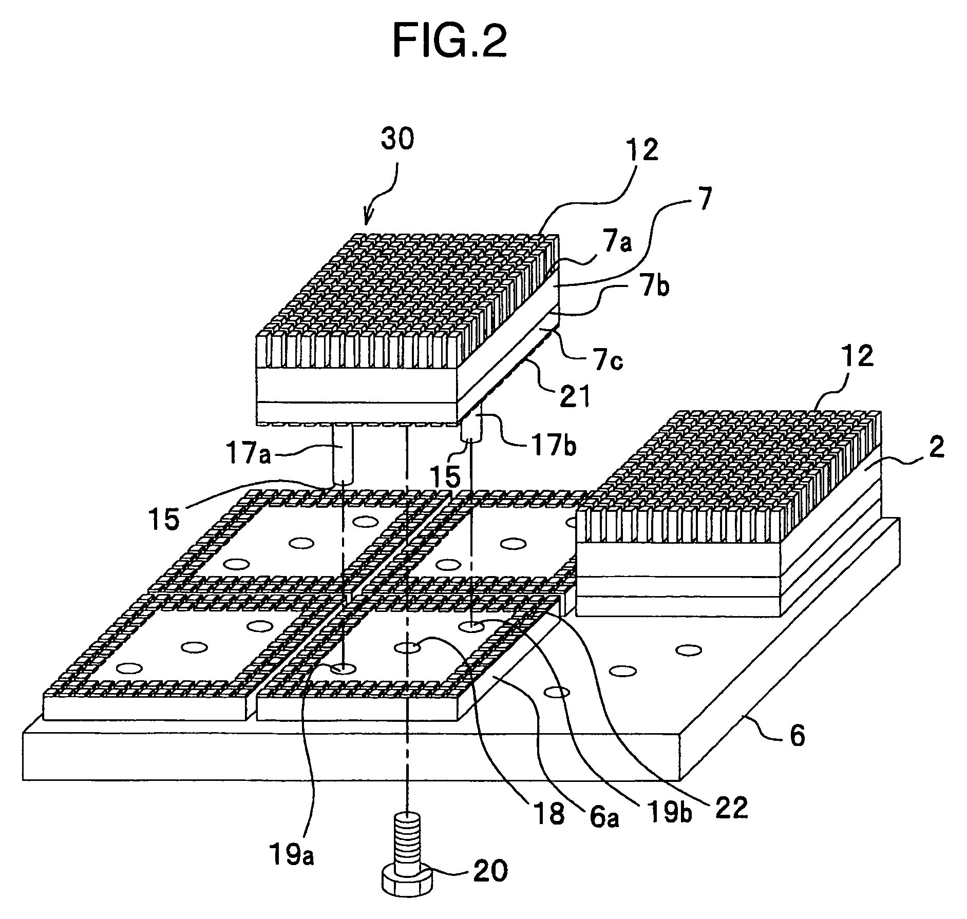
A radiological imaging apparatus comprising a semiconductor detector unit in which a plurality of semiconductor radiation detection elements are installed on a detector mounted substrate in a matrix to constitute a detector unit. A plurality of detector units are releasably mounted on a fixing substrate. This mounting is carried out mating a coupling screw with a threaded hole formed in the detector mounted substrate, the coupling screw being inserted through a through-hole formed in the fixing substrate. The detector mounted substrate is provided with a pair of positioning pins. The positioning pins are inserted into positioning holes, respectively, formed in the fixing substrate, to position the detector unit.

Description

BACKGROUND OF THE INVENTION[0001]The present invention relates to a radiation detection apparatus and a radiological imaging apparatus, and in particular, to radiation detection apparatus in which semiconductor radiation detection elements can be replaced with new ones, and a radiological imaging apparatus such as a single photon emission tomography apparatus (hereinafter referred to as a SPECT apparatus) and a positron emission tomography apparatus (hereinafter referred to as a PET apparatus which uses the radiation detection apparatus.[0002]Conventional radiation detectors detecting radiation such as a γ ray are known to use an NaI scintillator (JP-A-2000-241555 (paragraph 0019, FIG. 1)). In a gamma camera (a kind of radiological imaging apparatus) comprising an NaI scintillator, radiation (γ ray) is incident on the scintillator at an angle limited by a large number of collimators. The radiation thus interacts with an NaI crystal to emit scintillation light. The light reaches a ph...

Claims


Application Information

Patent Timeline
Patent Type & Authority Patents(United States)
IPC IPC(8): H01L25/00G01T1/24G01T1/161G01T1/29G01T7/00H01L27/14H01L31/09
CPCG01T1/2928
Inventor YOKOI, KAZUMAKITAGUCHI, HIROSHITSUCHIYA, KATSUTOSHIISHITSU, TAKAFUMIAMEMIYA, KENSUKE
Owner HITACHI LTD
Learn More