Holding device for fastening a fuel distributor to an internal combustion engine

a technology for holding devices and fuel distributors, which is applied in the direction of liquid fuel feeders, machines/engines, mechanical equipment, etc., can solve the problems of pressure pulsations which may generate noise, restrict the wiring space of fuel injection valves, etc., and achieve reliable protection of electrical cables, facilitate assembly, and low production cost

Active Publication Date: 2018-01-09
ROBERT BOSCH GMBH
View PDF9 Cites 3 Cited by
  • Summary
  • Abstract
  • Description
  • Claims
  • Application Information

AI Technical Summary

Benefits of technology

[0004]The example holding device according to the present invention and the example system according to the present invention may have the advantage of allowing a better development. In particular, the wiring of the fuel injection valves is able to be improved and reliable protection from damage can be ensured.
[0006]The fuel distributor able to be fastened to the internal combustion engine via one or more holding element(s) is used as fuel accumulator when in operation. Pressure fluctuations in the fuel distributor and in fuel injectors connected to the fuel distributor cause pressure pulsations which may generate noise. To dampen such pressure pulsations, it is advantageous that the holding element has a first half shell and a second half shell; that at least one elastic rib is provided in a holding region of the first half shell and at least one elastic rib is provided in a holding region of the second half shell, the elastic rib provided in the holding region of the first half shell and the elastic rib provided in the holding region of the second half shell circumferentially enclosing a tubular base element of the fuel distributor. The elastic ribs may be produced from a viscoelastic material. Oscillations produced by pressure pulsations are therefore able to be damped in an effective manner.
[0008]It may be advantageous if multiple holding elements are provided, the holding elements are disposed on the cable guide at a distance from each other, and the holding elements are at least indirectly connected to the cable guide. This makes it possible to reliably secure the cable guide to the internal combustion engine. The cable guide and the fuel distributor are thereby also positioned in a reliable manner in relation to the internal combustion engine. The electrical lines can be routed to the individual fuel injectors or the like via the cable guide. A compact design then results in the installed state, which also makes it easier to install further attachment components. Reliable protection of the electrical lines from the environment is ensured in addition.
[0010]In one modified development, it may be advantageous if a housing part is provided on the at least one holding element which includes a guide profile part and a pivotable cover part. The electrical cables can then be placed in the guide profile part during the assembly. It may also be advantageous if the cover part is connected to the guide profile part via a foil hinge. This facilitates the assembly, since the position of the cover part on the guide profile part is already predefined by the construction. A loss prevention for the cover part is provided in addition.
[0011]Once the electrical cables have been placed in the guide profile part, the cover part can be connected to the guide profile part by a snap-in connection, for example, so that the cover part is fixed in place in a closed pivot position. It is also advantageous here that at least one insertion rail is provided and that one end of the insertion rail is fixed in place between the cover part and the guide profile part in the closed pivot position of the cover part of the housing part provided on the holding element. This makes it possible to ensure reliable protection of the electrical cables.

Problems solved by technology

The fuel supply system described in U.S. Pat. No. 7,591,246 B2 may have the disadvantage that the space required for the wiring of the fuel injection valves is restricted by the holders.
Pressure fluctuations in the fuel distributor and in fuel injectors connected to the fuel distributor cause pressure pulsations which may generate noise.

Method used


Image

  • Holding device for fastening a fuel distributor to an internal combustion engine
  • Holding device for fastening a fuel distributor to an internal combustion engine
  • Holding device for fastening a fuel distributor to an internal combustion engine

Examples


Embodiment Construction

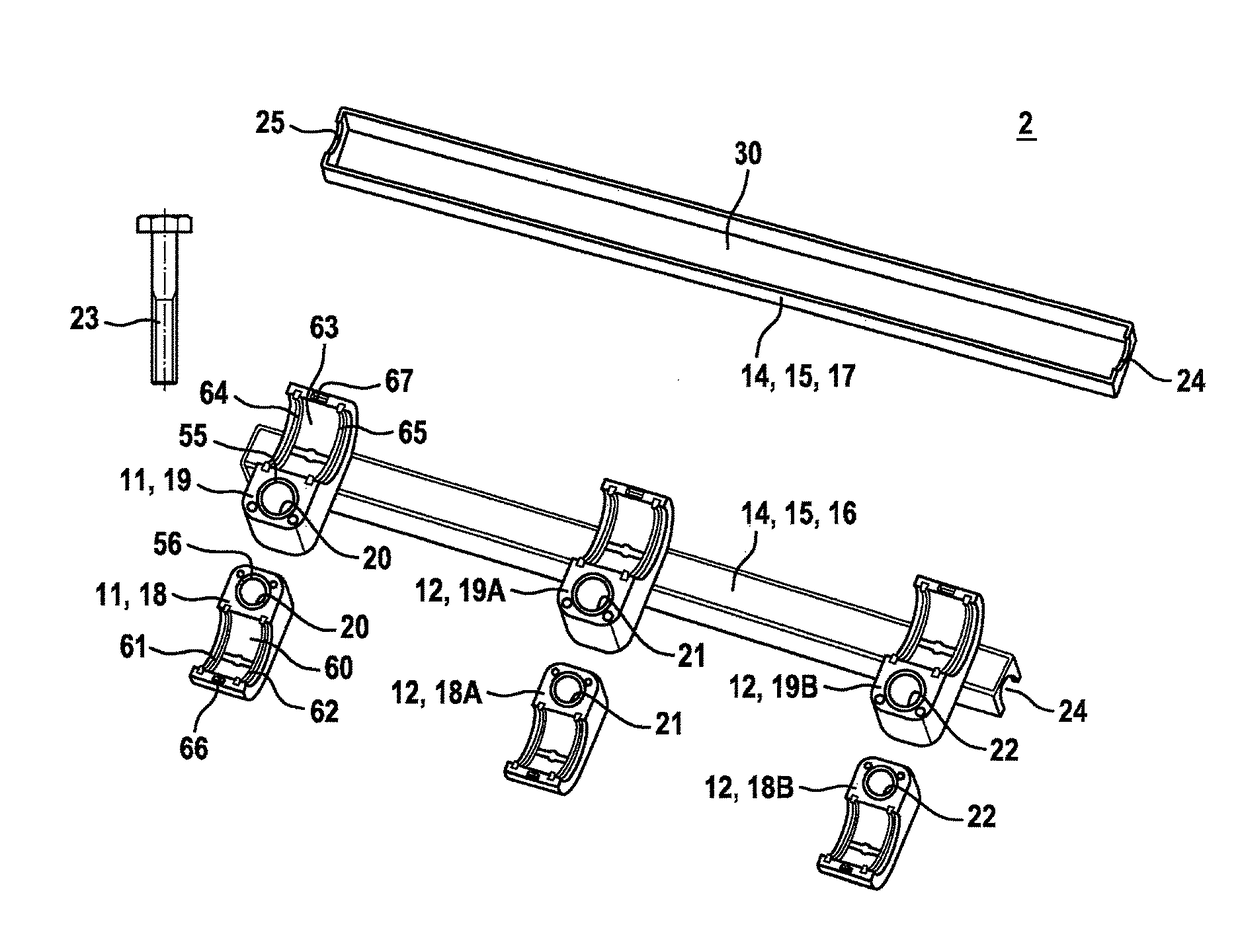
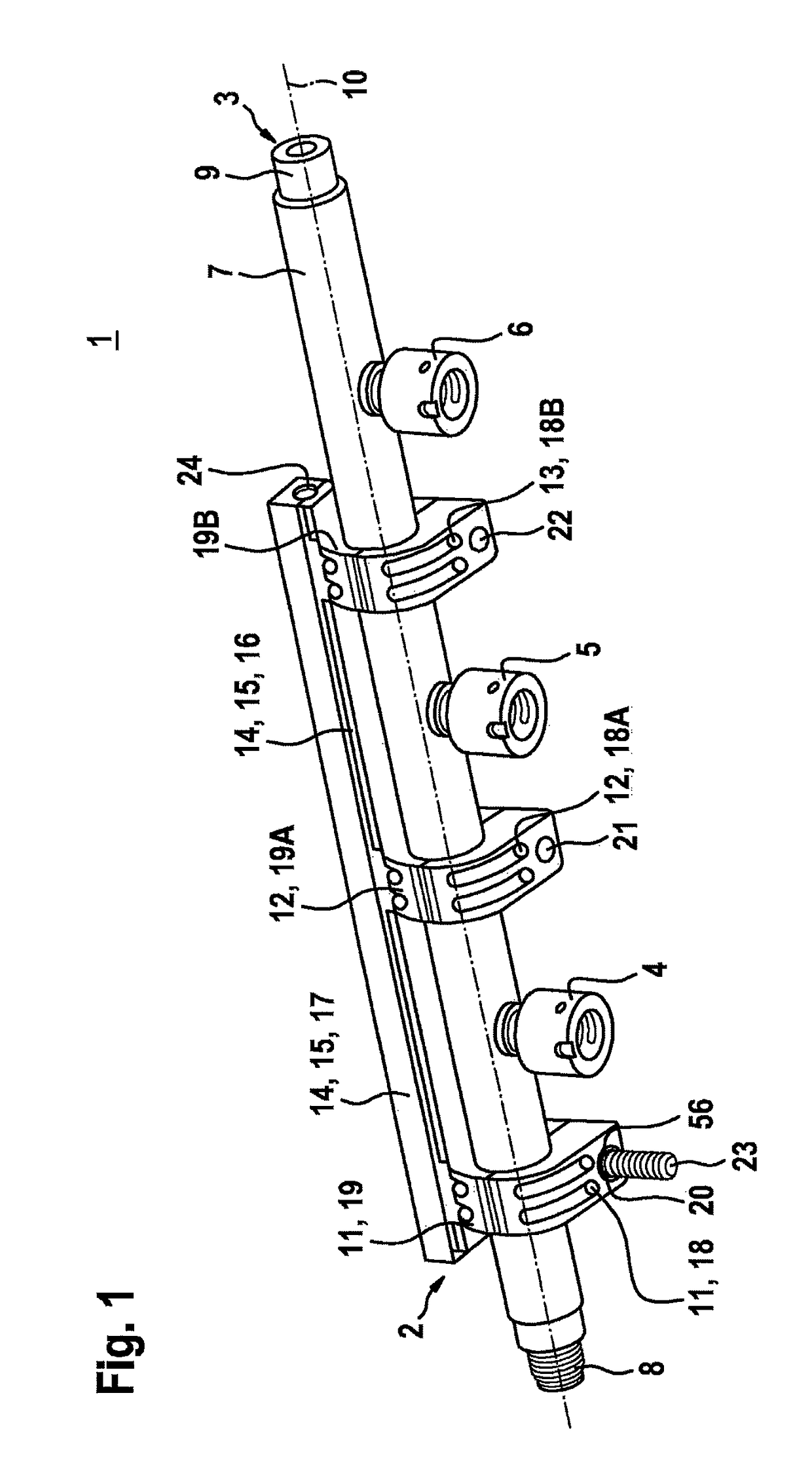
[0019]FIG. 1 shows a system 1 having a holding device 2 and a component 3 developed as fuel distributor 3, in a three-dimensional representation that corresponds to a first exemplary embodiment. In this exemplary embodiment, fuel distributor 3 is used for storing and distributing fuel to multiple fuel injectors, which are connected to fuel distributor 3 via cups 4, 5, 6 of fuel distributor 3. In this exemplary embodiment, fuel distributor 3 has a tubular base element 7. Holding device 2 is used in particular for fuel distributors 3 of this type. However, in one modified development component 3 may also be used for conveying other fluids. For example, component 3 may make it possible to conduct cooling water to be supplied to engines of hybrid vehicles.

[0020]Cups 4 through 6 are suitably connected to tubular base element 7. Furthermore, a connection thread 8 and an end piece 9 are provided on tubular base element 7. For example, a fuel line, which links fuel distributor 3 to a high-p...


PUM


Abstract

A holding device is used for fastening a fuel distributor to an internal combustion engine. A plurality of holding elements is provided, which are able to be fixed in place on the internal combustion engine via a fastener. A cable guide is provided in addition. The holding elements are connected to the cable guide. In addition, a system having such a holding device and a fuel distributor for conveying fuel are provided.

Description

FIELD[0001]The present invention relates to a holding device for fastening a component, in particular a fuel distributor, to an internal combustion engine. In particular, the present invention relates to the field of fuel injection systems of internal combustion engines, where fuel under high pressure is injected into assigned combustion chambers of the internal combustion engine via fuel injection valves.BACKGROUND INFORMATION[0002]A fuel supply system having multiple holders is described in U.S. Pat. No. 7,591,246 B2. The individual holder has a first holder part and a second holder part, the two parts cooperating in such a way that they connect a fuel rail to a cylinder head in a reversible manner. A fastening screw which screws the holder parts to the cylinder head is provided for this purpose.[0003]The fuel supply system described in U.S. Pat. No. 7,591,246 B2 may have the disadvantage that the space required for the wiring of the fuel injection valves is restricted by the hold...

Claims


Application Information

Patent Timeline
Patent Type & Authority Patents(United States)
IPC IPC(8): F02B67/00F02M61/14F02M69/46F02B75/22F02B67/06F02B63/04F02B67/04
CPCF02M69/465F02M61/14F02B63/04F02B67/00F02M2200/857F02B67/06F02B75/22F02M2200/803F02B67/04
Inventor REHWALD, ANDREASSPINNER, MARC
Owner ROBERT BOSCH GMBH
Why Eureka
Try Eureka