
Airplane wing, an airplane and a flap system

a flap system and airplane technology, applied in the field of airplane wings, can solve the problems of increased drag, increased drag, and increased risk of damage, and achieve the effect of reducing damage risk and minimizing friction

Active Publication Date: 2018-01-16
FOKKER AEROSTRUCTURES
View PDF15 Cites 1 Cited by
  • Summary
  • Abstract
  • Description
  • Claims
  • Application Information

AI Technical Summary

Benefits of technology

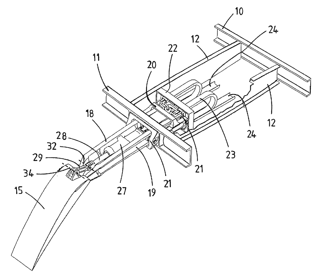
[0013]According to the invention, the flap can be extended rearward by operating the first actuator and the flap can be rotated upward or downward by operating the second actuator. A downwardly rotated position of the flap increases wing area and also the mean camber line of the airplane wing, thereby increasing the coefficient of lift. Thus, the airplane wing can be continuously adapted between at least a first configuration having a first coefficient of lift and a second configuration having a second coefficient of lift that is greater than the first coefficient of lift.
[0026]In a preferred embodiment, the main wing has a chord which is defined by a straight line between the leading edge and the trailing edge of the main wing, and wherein the second actuator is configured to rotate the flap about the rotation axis in an upward direction and in a downward direction relative to the chord of the main wing. Using the control device for the second actuator, the flap can be controlled to rotate about the rotation axis either in an upward direction or a downward direction with respect to the chord of the main wing, i.e. the flap can be selectively controlled in both directions. Thus, the flap can be used as aileron, i.e. the flap constitutes a “flaperon”. For example, the deployment angle of the flap is at least 40 degrees downwards and at least 3 degrees upwards. As the rotation of the flap can be controlled independently from the extension of the flap track member, the flap can also be used as aileron when the flap track member is retracted and the flap has its stowed position. In this case, the flap can be used to fine-tune the airplane for minimum drag and / or minimum fuel consumption in cruise flight conditions.

Problems solved by technology

The second auxiliary wing at the rear of the first auxiliary wing, and the selection mechanism of levers, rods, guide rails, pivotal connections and slidable connections are complicated, generally unreliable and relatively heavy.
In addition, the selection mechanism in its retracted position protrudes below the main wing, which causes increased drag and a higher risk of damage, for example by bird impacts.

Method used


Image

  • Airplane wing, an airplane and a flap system
  • Airplane wing, an airplane and a flap system
  • Airplane wing, an airplane and a flap system

Examples


Embodiment Construction

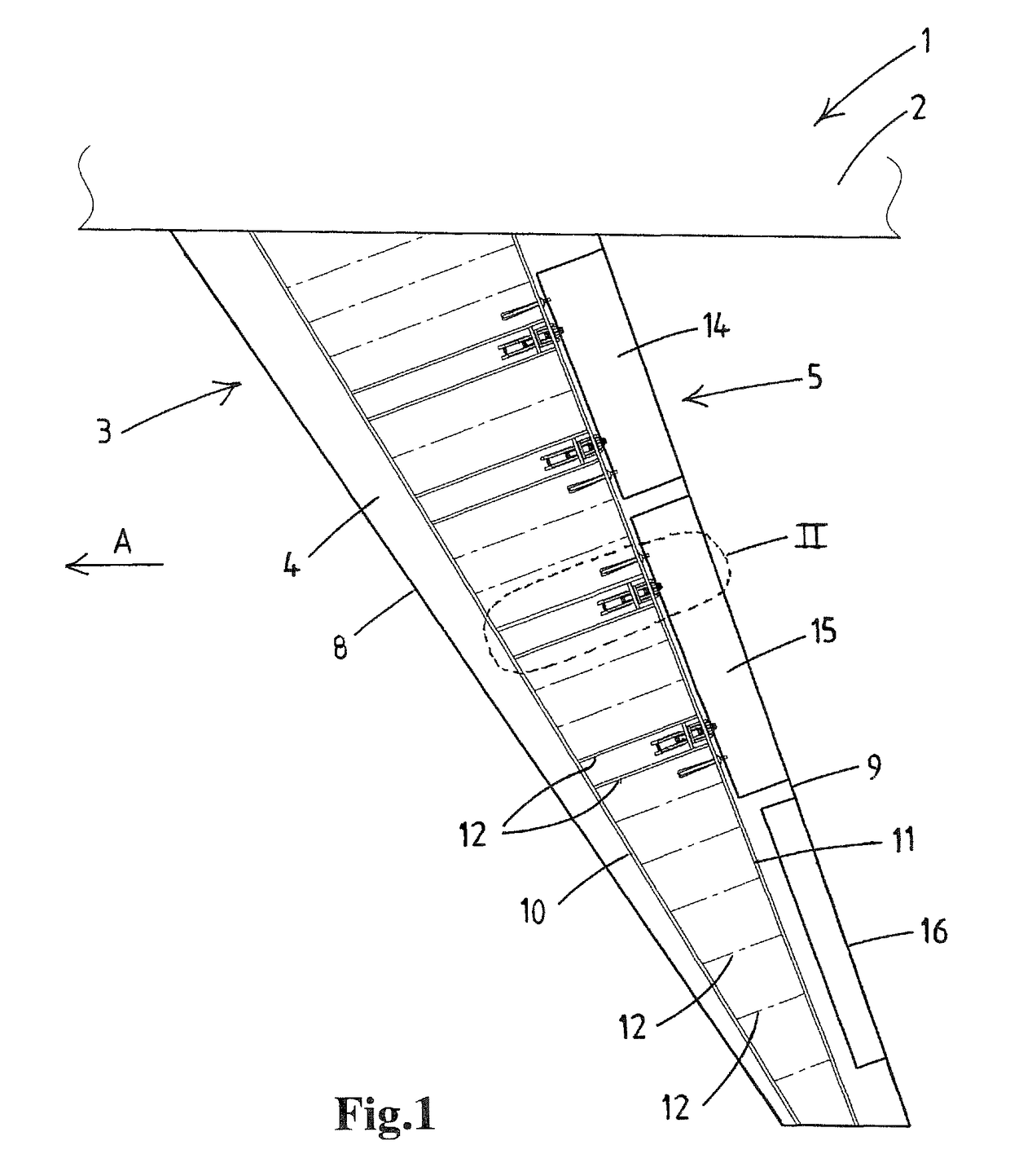
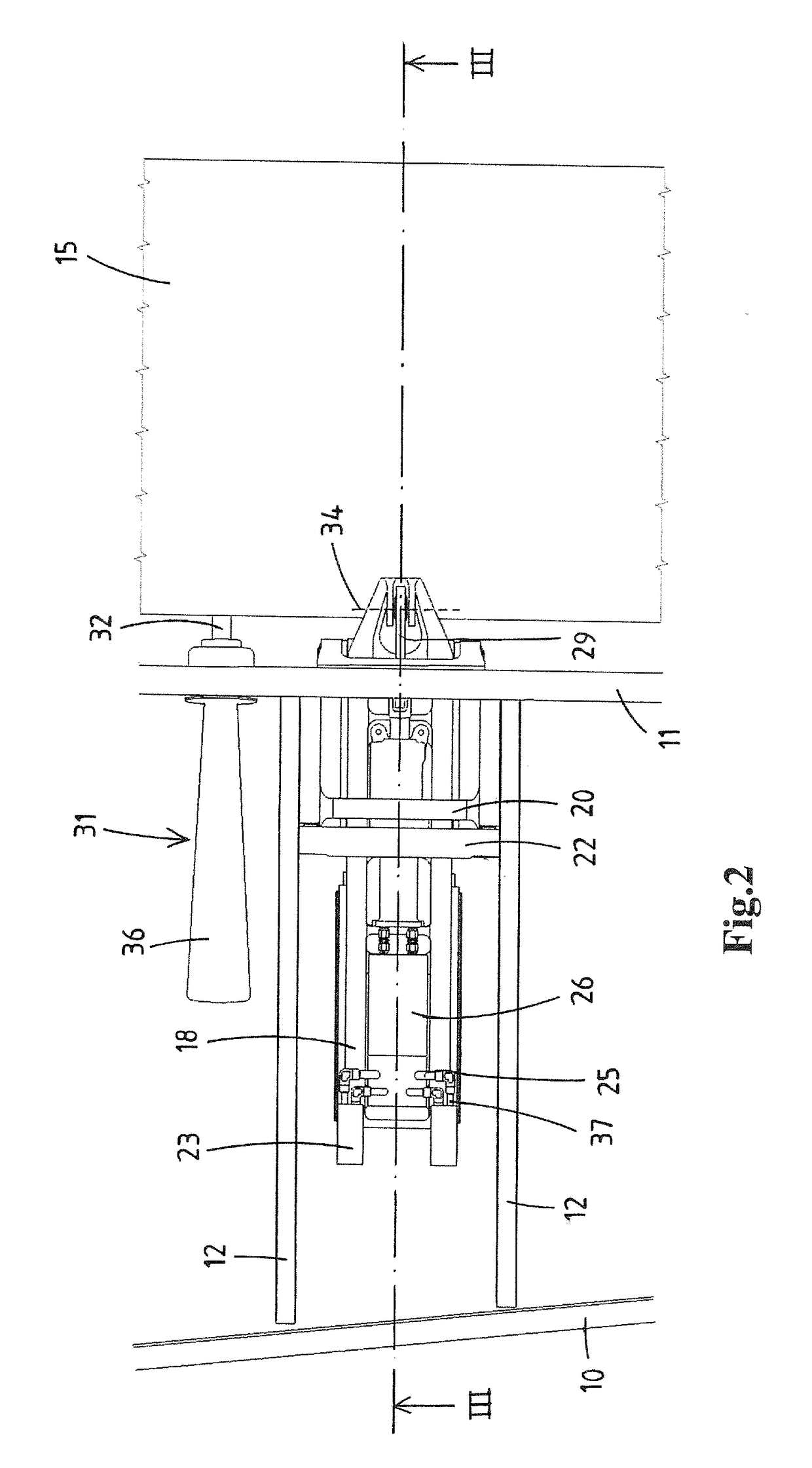
[0043]Referring now to the exemplary embodiment illustrated in the drawings, FIG. 1 shows a schematic representation of part of a conventional airplane 1 comprising a fuselage 2 and two airplane wings 3 (only one airplane wing is illustrated in FIG. 1). It should be understood that the airplane wings 3 are symmetrical about the fuselage 2. The flight direction of the airplane 1 and the airplane wing 3 is indicated by arrow A. Each airplane wing 3 includes a main wing 4 and a flap system 5. The flap system 5 is compatible with or adaptable to modern airplanes.

[0044]The main wing 4 includes a leading edge 8 and a trailing edge 9. The main wing 4 has an airfoil shape in cross-section. A chord is defined by a straight line between the leading edge 8 and the trailing edge 9. The structure of the main wing 4 comprises a front spar 10 and a rear spar 11 that run in the spanwise direction of the main wing 4. A plurality of wing ribs 12 are spaced relative to each other. Each wing rib 12 ext...


PUM


Abstract

An airplane wing comprises a main wing and a flap system that has a flap at the trailing edge of the main wing. An elongate flap track member is connected to the main wing in such a manner that it can be moved substantially in its longitudinal direction and is guided by supporting bearing elements relative to the main wing between a forward retracted position and a rearward extended position. The flap is rotatably connected to the rear end of the flap track member in such a manner that it can rotate about a rotation axis that extends substantially parallel to the trailing edge of the main wing, so that the flap moves together with the flap track member when the flap track member is moved and so that the flap can be rotated about the rotation axis mechanically independently of the movement of the flap track member. The flap system comprises an actuator system having two actuators. The first actuator is connected to the main wing and has an engagement member that engages the flap or the flap track member for moving the flap together with the flap track member so that the flap track member is move able between its retracted position and its extended position. The second actuator is connected to the flap track member so that the second actuator moves together with the flap track member when the flap track member is moved by means of the first actuator. The second actuator has an engagement member that engages the flap for rotating the flap about the rotation axis.

Description

FIELD OF THE INVENTION[0001]The invention relates to an airplane wing, comprising:[0002]a main wing having a trailing edge,[0003]a flap system, the flap system comprising:[0004]a flap at the trailing edge of the main wing,[0005]supporting bearing elements being fixed to the main wing, in particular within the main wing, and[0006]an elongate flap track member being connected to the main wing in such a manner that it can be moved substantially in its longitudinal direction and is guided by the supporting bearing elements relative to the main wing between a forward retracted position and a rearward extended position, the flap track member having a front end and a rear end,the flap being rotatably connected to the rear end of the flap track member in such a manner that it can rotate about a rotation axis that extends substantially parallel to the trailing edge of the main wing, so that the flap moves together with the flap track member when the flap track member is moved and so that the...

Claims


Application Information

Patent Timeline
Patent Type & Authority Patents(United States)
IPC IPC(8): B64C9/38B64C9/18B64C13/00B64C9/16
CPCB64C9/38B64C9/16B64C13/00B64C9/18Y02T50/32Y02T50/30
Inventor BASTIAANSEN, ADRIANUS MARINUS FRANCISCUSSCHOONHOVEN, MICHEL
Owner FOKKER AEROSTRUCTURES
Learn More