Tensioner with increased damping and arm on base cup configuration

a technology of damping and arm, which is applied in the direction of belt/chain/gearing, machine/engine, etc., can solve the problems of loss of belt tension, loss of synchronization between components such as valves, and catastrophic damage to engines,

Active Publication Date: 2018-01-16
LITENS AUTOMOTIVE INC
View PDF101 Cites 9 Cited by
  • Summary
  • Abstract
  • Description
  • Claims
  • Application Information

AI Technical Summary

Problems solved by technology

This results in a loss of the synchronization between components such as the valves, with the engine.
Such a loss of synchronization can result in catastrophic damage to the engine due to collisions between the valves and the pistons in some engines (those that have an ‘interference’ design), and can lead to damage even in engines that do not incorporate an ‘interference’ design.
Without sufficient damping of the tensioner arm, sudden changes in belt tension can result the arm failing to sufficiently follow the belt, which can lead to the aforementioned loss of belt tension.
Ways of achieving suitable damping have been proposed in the past, however, they typically result in an expensive tensioner, which is undesirable.

Method used


Image

  • Tensioner with increased damping and arm on base cup configuration
  • Tensioner with increased damping and arm on base cup configuration
  • Tensioner with increased damping and arm on base cup configuration

Examples


Embodiment Construction

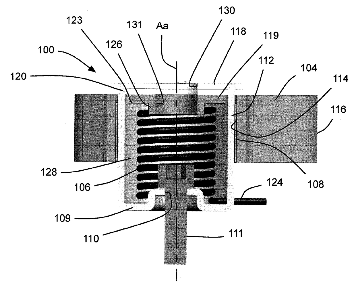
[0022]Reference is made to FIG. 1, which shows a crankshaft 910 from an engine 913 from a vehicle (not shown). It will be noted that the engine 913 is shown as a simple rectangle for illustrative purposes. It will be understood that the engine 913 may have any suitable shape. The vehicle may be any suitable vehicle, such as an automobile, a truck, a van, a minivan, a bus, an SUV, a military vehicle, a boat or any other suitable vehicle. A timing belt 914 is shown extending between a pulley 912 on a crankshaft 910 of the engine 913, and a pair of pulleys 904a and 904b on camshafts 905a and 905b, so as to transfer rotary power from the crankshaft 910 to the camshafts 905a and 905b.

[0023]A tensioner 100 is shown mounted to the engine 913, between the crankshaft 910 and the camshaft 905a for embodiments in which the timing belt is immersed in an oil bath (referred to as a belt-in-oil arrangement). The tensioner 100 acts to maintain tension in the timing belt 914. An idler is shown at 9...


PUM


Abstract

In an aspect, a tensioner is provided for maintaining tension in an endless drive member in a belt-in-oil drive system. The tensioner includes a base that is mountable to a stationary structure and that has a circumferential wall that defines an arm pivot axis, an arm having a radially inner arm surface, and an endless drive member engagement surface that is engageable with an endless drive member, a bushing positioned between the radially inner arm surface and the circumferential wall of the base cup, and a tensioning spring. The arm is supported on the base cup via the bushing. The tensioning spring is positioned to bias the arm in a first direction about the arm pivot axis.

Description

CROSS-REFERENCE TO RELATED APPLICATIONS[0001]This application claims priority from U.S. Provisional Patent Application No. 61 / 876,502 filed Sep. 11, 2013, the contents of which are incorporated herein in their entirety.FIELD OF INVENTION[0002]This disclosure relates generally to the field of tensioners for endless drive members such as chains or timing belts.BACKGROUND OF INVENTION[0003]Many engines in vehicles today use a timing belt to drive certain components that require specific synchronization with the rotation of the engine, such as the camshafts which control the opening and closing of the valves to the cylinders. Tensioners used for maintaining tension in the timing belts serve a critical role, since a loss of tension in a timing belt can lead to the timing belt skipping teeth on the toothed pulleys they are connected to. This results in a loss of the synchronization between components such as the valves, with the engine. Such a loss of synchronization can result in catastr...

Claims


Application Information

Patent Timeline
Patent Type & Authority Patents(United States)
IPC IPC(8): F16H7/10F16H7/12F16H7/08F02B67/06
CPCF16H7/1218F16H7/0831F16H2007/084F16H2007/081F02B67/06
Inventor FRANKOWSKI, MAREK
Owner LITENS AUTOMOTIVE INC
Why Eureka
Try Eureka