
Controlled switching devices and method of using the same

a switching device and control technology, applied in the field of electric engineering, can solve problems such as major blackout, reducing system reliability, and non-optimal operation of installations, and achieve the effect of reducing inrush current and fast switching of capacitive loads of electrical circuits

Active Publication Date: 2018-01-16
VIZIMAX
View PDF9 Cites 3 Cited by
  • Summary
  • Abstract
  • Description
  • Claims
  • Application Information

AI Technical Summary

Benefits of technology

The present invention provides a method for reducing the sudden surge of electrical current, called inrush current, when a capacitive load is connected to a circuit breaker. The method involves the use of a controlled switching device that sends a command to the circuit breaker to synchronize its operation and reduce the surge of current. This allows for the fast switching of capacitive loads, and can also help to prevent damage to the circuit components. In addition, the invention provides an electrical circuit that includes a breaker and a controlled switching device for the purpose of reducing inrush current during the connection of capacitive loads.

Problems solved by technology

The consequences of such inrush current may be critical as they may damage the equipment, hence reducing the reliability of the system.
Furthermore, the resulting transients may travel on the lines and trip a protection reducing then the stability of the network and potentially leading into a major blackout.
Furthermore, the 15 minute waiting time for capacitor discharge is problematic as it does not allow the power system and DER operators to switch at their convenience resulting in a non-optimal operation of their installations.

Method used


Image

  • Controlled switching devices and method of using the same
  • Controlled switching devices and method of using the same
  • Controlled switching devices and method of using the same

Examples


Embodiment Construction

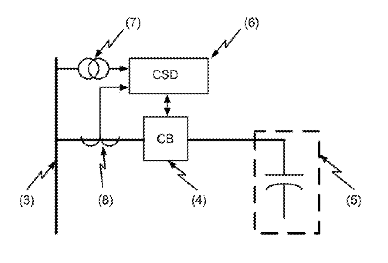
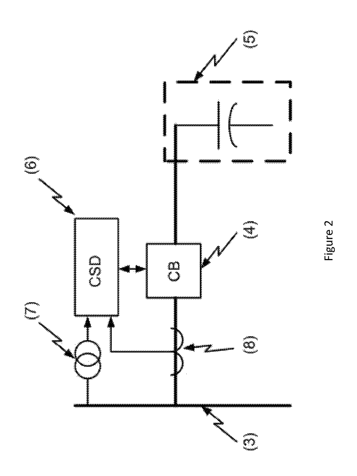
[0032]A novel controlled switching device and method using the same will be described hereinafter. Although the invention is described in terms of specific illustrative embodiment(s), it is to be understood that the embodiment(s) described herein are by way of example only and that the scope of the invention is not intended to be limited thereby.

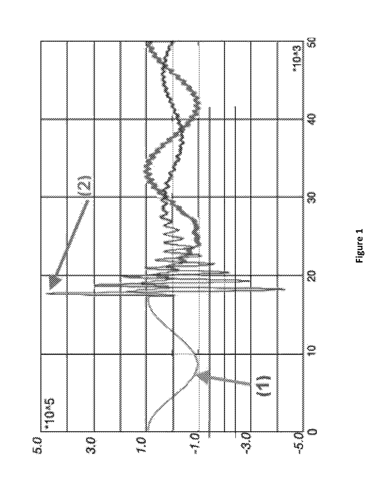
[0033]This invention relates to the fast switching of capacitive loads by controlling the operations of a CB to mitigate and / or eliminate the inrush current using a CSD, wherein the CSD automatically determines the optimal electrical switching angle of the CB according to the magnitude and the polarity of residual DC voltage charges trapped in the load. The CSD evaluates or measures the residual DC voltage on the capacitive load. A technique for evaluating the DC residual voltage (Vi) in the capacitive loads resulting from the circuit breaker opening as well as a technique to evaluate the varying DC residual voltage over the time are also di...


PUM


Abstract

It is disclosed a technique in which Controlled Switching Devices (CSDs) are used to control medium and high voltage circuit breakers to mitigate switching transients. This invention describes a method for controlling the closing of a circuit breaker to mitigate and / or eliminate the inrush current in capacitive loads such as capacitor banks and filters by taking into account the residual DC voltage charges that may be present in the load. It is disclosed a method to perform fast switching operations on capacitive loads and therefore eliminate the load discharge period.

Description

CROSS-REFERENCE TO RELATED APPLICATIONS[0001]The present patent application claims the benefits of priority of U.S. Patent Application No. 61 / 919,617 entitled “CONTROLLED SWITCHING DEVICES AND METHOD OF USING THE SAME” and filed at the United-States Patent and Trademark Office on Dec. 20, 2013, the content of which is incorporated herein by reference.FIELD OF THE INVENTION[0002]The present invention generally relates to the field of electrical engineering. More particularly, the invention relates to a device and method for fast switching of capacitive loads by controlling the operations of a circuit breaker to mitigate or eliminate the inrush current by taking into account the residual voltage that may be present in this type of load. Examples of capacitive loads are capacitor banks used for reactive compensation, capacitors in harmonic filters and isolated power lines. The present invention also relates to Controlled Switching Devices (CSDs) and methods for using the same.BACKGROUN...

Claims


Application Information

Patent Timeline
Patent Type & Authority Patents(United States)
IPC IPC(8): H02J7/00H02J3/24H01H9/56
CPCH01H9/56H02J7/0068H02J3/24
Inventor TAILLEFER, PIERRELACROIX, MARC
Owner VIZIMAX
Learn More