Multipole PCB with small robotically installed rod segments

a technology of robotic installation and multi-pole pcb, which is applied in the direction of particle separator tube details, sustainable manufacturing/processing, and final product manufacturing, etc., can solve the problem of increasing the number of elements that need to be machined and aligned

Active Publication Date: 2018-01-16
THERMO FINNIGAN +1
View PDF8 Cites 29 Cited by
  • Summary
  • Abstract
  • Description
  • Claims
  • Application Information

AI Technical Summary

Problems solved by technology

Bent rods or improperly aligned rods can lead to asymmetries in the electric field that can cause desirable ions to

Method used


Image

  • Multipole PCB with small robotically installed rod segments
  • Multipole PCB with small robotically installed rod segments
  • Multipole PCB with small robotically installed rod segments

Examples


Embodiment Construction

[0025]Embodiments of systems and methods for ion separation are described herein.

[0026]The section headings used herein are for organizational purposes only and are not to be construed as limiting the described subject matter in any way.

[0027]In this detailed description of the various embodiments, for purposes of explanation, numerous specific details are set forth to provide a thorough understanding of the embodiments disclosed. One skilled in the art will appreciate, however, that these various embodiments may be practiced with or without these specific details. In other instances, structures and devices are shown in block diagram form. Furthermore, one skilled in the art can readily appreciate that the specific sequences in which methods are presented and performed are illustrative and it is contemplated that the sequences can be varied and still remain within the spirit and scope of the various embodiments disclosed herein.

[0028]All literature and similar materials cited in thi...


PUM


Abstract

A radio frequency multipole assembly includes first and second printed circuit boards. Each printed circuit board includes a substrate, at least two rows of conductive pads, and a plurality of tiles affixed to the conductive pads to form at least two radio frequency rods of a radio frequency multipole. The first and second printed circuit boards are arranged with the radio frequency rods towards each other and aligned to for the radio frequency multipole.

Description

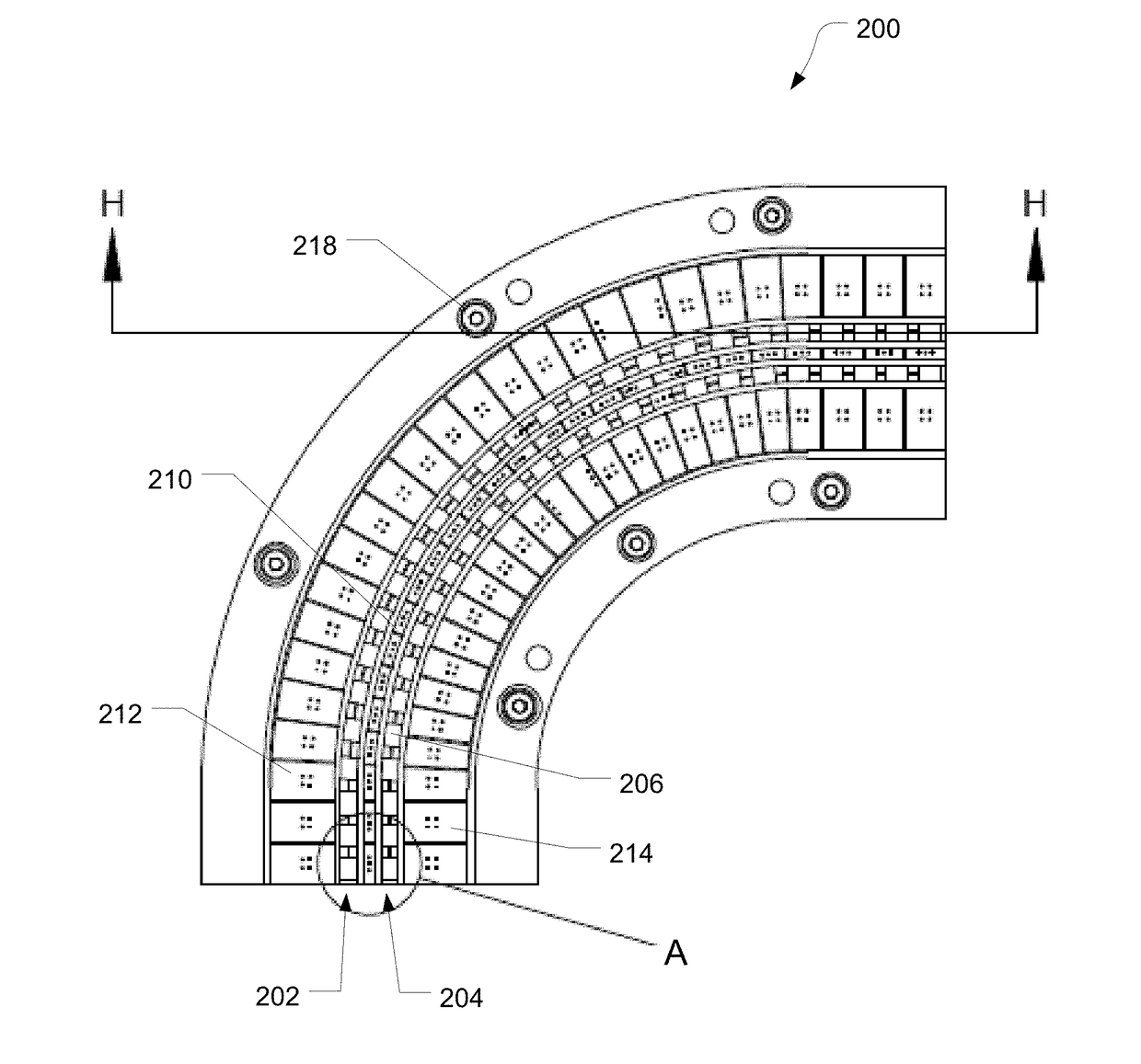
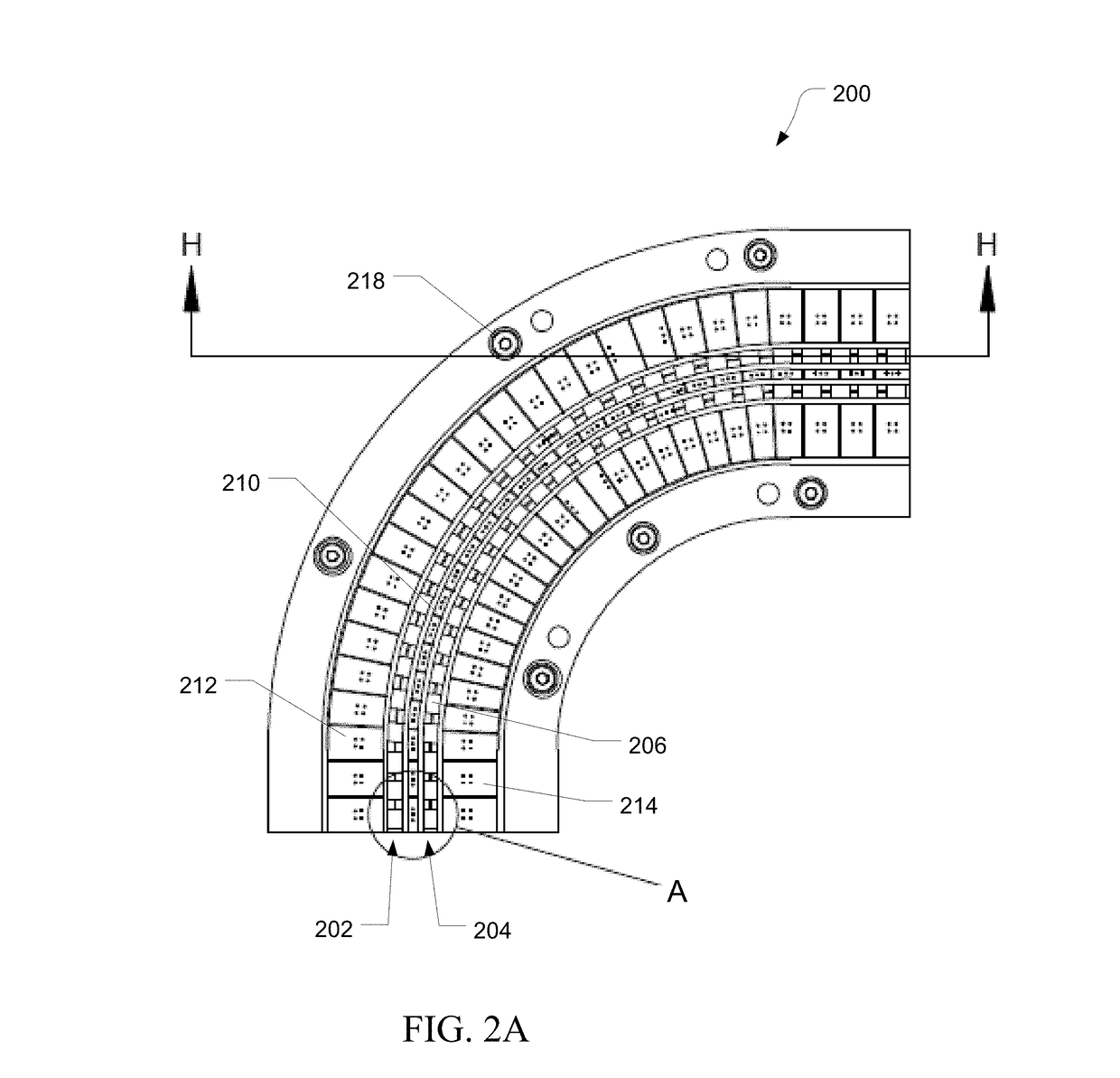
FIELD[0001]The present disclosure generally relates to the field of mass spectrometry including multipole PCBs with small robotically installed rod segments.INTRODUCTION[0002]Multipoles are generally created using rods arranged around a central axis. They can be used as ion guides, quadrupole mass filters, collision cells, and ion traps. Alternating electric fields (RF potentials) can be applied to the rods to focus ions along a central axis of the multipole. To achieve a high degree of focusing, it is necessary to precisely machine and align the rods. Bent rods or improperly aligned rods can lead to asymmetries in the electric field that can cause desirable ions to be ejected from the multipole.[0003]In addition to monolithic rods, segmented rods have been used for the creation of multipoles. However, this increases the number of elements that need to be machined and aligned. Good results for segmented rods have been achieved by machining a monolithic rod and then cutting the rod i...

Claims


Application Information

Patent Timeline
IPC IPC(8): H01J29/26H01J49/42H01J49/06
CPCH01J49/063H01J49/4215H01J49/4225H01J49/4255H05K1/0243H05K1/111H05K1/144H05K1/181H05K2201/042H05K2201/09027H05K2201/09409H05K2201/10098H05K2201/10522H05K2203/167Y02P70/50
Inventor QUARMBY, SCOTT T.HAUSCHILD, JAN-PETERHITCHCOCK, JAMES M.
Owner THERMO FINNIGAN
Why Eureka
Try Eureka