
Method for determining channel quality indicator, base station and user equipment therefor

a channel quality indicator and channel quality technology, applied in the direction of signalling characterisation, site diversity, baseband system details, etc., can solve the problems of large macro load, inefficient use of lpns spectral resources, and the inability to select cqi accurately, so as to achieve the effect of fixing the performance loss

Active Publication Date: 2018-01-16
SUN PATENT TRUST
View PDF26 Cites 0 Cited by
  • Summary
  • Abstract
  • Description
  • Claims
  • Application Information

AI Technical Summary

Benefits of technology

The patent text describes a method where a user equipment (UE) can adjust the quality of service (QoS) it provides based on instructions from a base station. This allows for better traffic offloading and reduces performance loss. The technical effect of this invention is improved efficiency and performance of wireless networks.

Problems solved by technology

Because of the large coverage area of the macro and the small coverage area of the LPN, a large number of UEs are in the coverage area of the macro and will be served by the macro while only a small portion of UEs will be served by the LPNs, which results in a heavy load on the macro and an inefficient use of spectral resources of LPNs.
Therefore, there is a problem how to decide which base station cooperation should be assumed in CQI calculation.
In short, the problem is how to decide which CQI should be reported.
However the UE selected CQI could be very off because the traffic load conditions at base stations are unknown to the UE.
If the UE merely selects the highest CQI(s), then it is likely that the highest CQI(s) cause heavy traffic load at the macro, which means that traffic offloading operation at base stations is not possible.
However, this solution has following defects.
On one hand, the base station selection is not optimal because the base station does not know which CQI(s) are the highest at UE.
Therefore base station selection does not guarantee optimal performance.
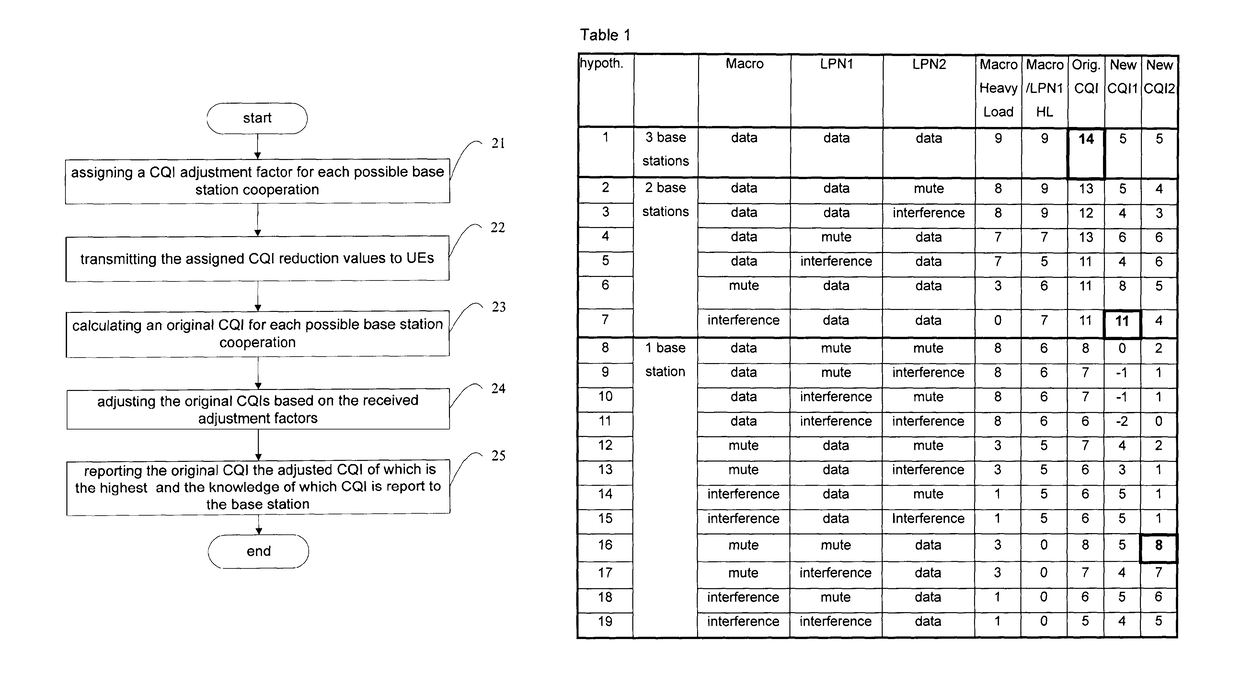
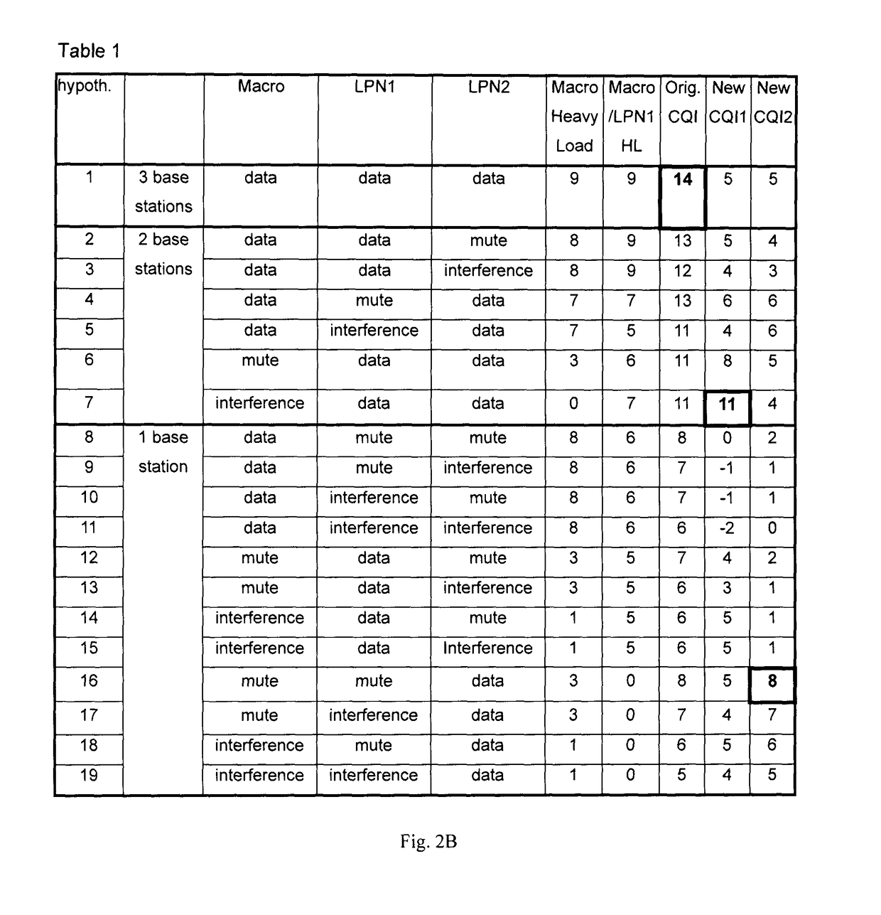
On the other hand, even if in some case the base station has knowledge of which CQI(s) are the highest, the downlink signalling overhead is too much because highest CQI(s) may change dynamically.
Because the highest CQI may changes much faster than RRC configuration, the semi-statically configuration from base station maybe not yields best performance.

Method used


Image

  • Method for determining channel quality indicator, base station and user equipment therefor
  • Method for determining channel quality indicator, base station and user equipment therefor
  • Method for determining channel quality indicator, base station and user equipment therefor

Examples


first embodiment

[0022]A method of dynamically determining Channel Quality Indicators (CQI) to be reported by User Equipments (UE) is described in the present embodiment. According to this method, the UE calculates original CQIs according to CQI calculation hypotheses corresponding to various base station cooperations; adjusts the original CQIs based on adjustment factors indicated by the base station; and report the proper CQIs. Through this method, when the adjustment factors reflects the load conditions at base stations, the UE can report CQIs by taking into account the traffic load conditions as indicated by the base station. Therefore, the traffic offloading is enabled and the defect of performance loss can be avoided.

[0023]FIG. 2A is a diagram showing a flow chart of a method of dynamically determining CQIs to be reported according to the first embodiment of the present disclosure. In the following, the method will be described in detail with reference to FIG. 2A, taking a macro and two LPNs (...

second embodiment

[0033]The first embodiment is described above by taking the CQI reduction value as an example of the adjust factor. In fact, the adjust factor can be any other types of value, such as weighting coefficient. For example, if the macro is heavily loaded, while LPN1 and LPN2 are lightly loaded, the base station cooperations that the macro transmits data therein may be configured with a small weighting coefficient. And the more heavily the macro is loaded, the smaller weighting coefficient may be assigned to the related base station cooperation. In this instance, in step 24, the UE adjusts the original CQIs by multiplying each original CQI by a corresponding weighting coefficient. The operations in other steps are the same with those in the first embodiment, and thus will not be described repeatedly herein.

third embodiment

[0034]The method of the present embodiment is substantially the same as that of the first embodiment, except that the base station transmits to UEs multiple sequences of adjustment factors. Each sequence may correspond to different load conditions. Specifically, in the first embodiment, a sequence of adjustment factors is assigned to various possible base station cooperations, while in the present embodiment, multiple sequences, for example two sequences, of adjustment factors are assigned to various possible base station cooperations, wherein one sequence corresponds to the macro heavily loaded, and another one corresponds to the macro lightly loaded. The two sequences may have some common part, and thus in step 22, possibly only the first sequence and the different parts of the second sequence will be transmitted to UEs. In step 24, the UE adjusts the original CQIs based on said two sequences of adjustment factors respectively. Then, in step 25, the UE reports one highest CQI with...


PUM


Abstract

A base station and a related method are provided. The base station includes a transmitter which, in operation, transmits, to a user equipment (UE), values configured for different base station coordination types, respectively, wherein each of the base station coordination types defines which base stations among multiple base stations perform coordinated transmission in that base station coordination type. The base station further includes a receiver which, in operation, receives a channel quality indicator (CQI) reported from the UE, wherein the CQI is calculated at the UE in reference to the values.

Description

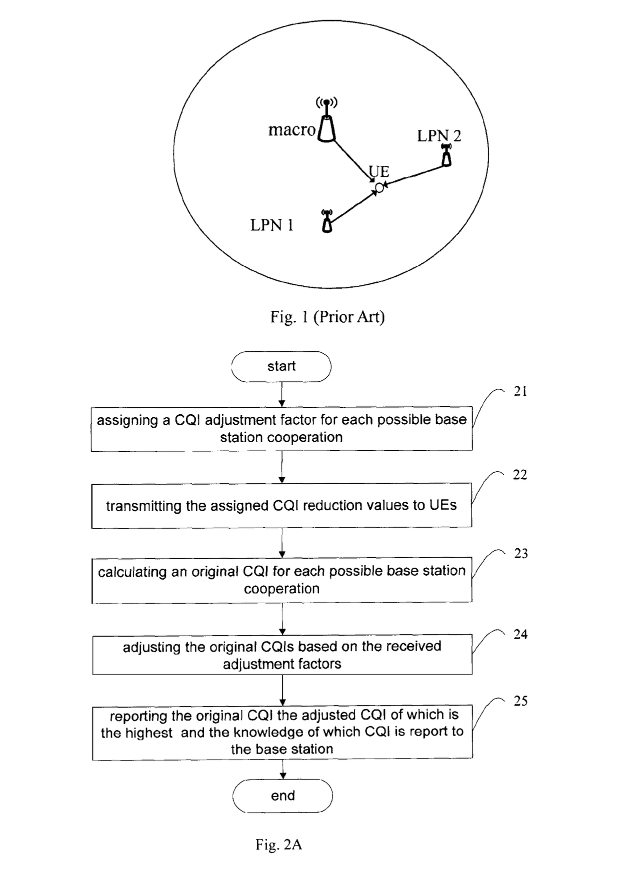
TECHNICAL FIELD[0001]The present disclosure relates to Channel Quality Indicator (CQI) determination and traffic offloading in base station cooperation.BACKGROUND[0002]Base station cooperation in a heterogeneous network is an important means to improve the performance, e.g., throughput, of communication systems. In the heterogeneous network, the transmission power from different base stations may be very different and accordingly the coverage areas of the base stations are different. Specifically, the coverage area of a high power base station, i.e. a high power node (macro) is much larger than the coverage area of a low power base station, i.e. a lower power node (LPN), and the coverage area of the LPN may overlap with that of the macro, as shown in FIG. 1. Because of the large coverage area of the macro and the small coverage area of the LPN, a large number of UEs are in the coverage area of the macro and will be served by the macro while only a small portion of UEs will be served...

Claims


Application Information

Patent Timeline
Patent Type & Authority Patents(United States)
IPC IPC(8): H04W72/04H04B7/06H04B7/024H04L1/00H04L5/00H04W28/08H04L25/02H04W16/32
CPCH04W72/0413H04B7/024H04B7/0632H04L1/0015H04L5/0035H04L1/0026H04W28/08H04L5/0075H04L25/0208H04W16/32H04L25/0204H04W28/18H04W24/10H04W72/21
Inventor TONG, HUIHOSHINO, MASAYUKIIMAMURA, DAICHIXU, MING
Owner SUN PATENT TRUST
Learn More