
Networked light control system and method

a technology of networked lights and control systems, applied in lighting apparatus, electric lighting sources, electric light sources, etc., can solve problems such as inability to turn off networked lights, software running on the controller can crash, and consumption of energy to power lights

Active Publication Date: 2018-01-16
GE LIGHTING SOLUTIONS LLC
View PDF7 Cites 1 Cited by
  • Summary
  • Abstract
  • Description
  • Claims
  • Application Information

AI Technical Summary

Benefits of technology

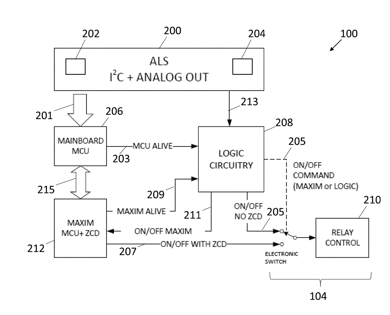
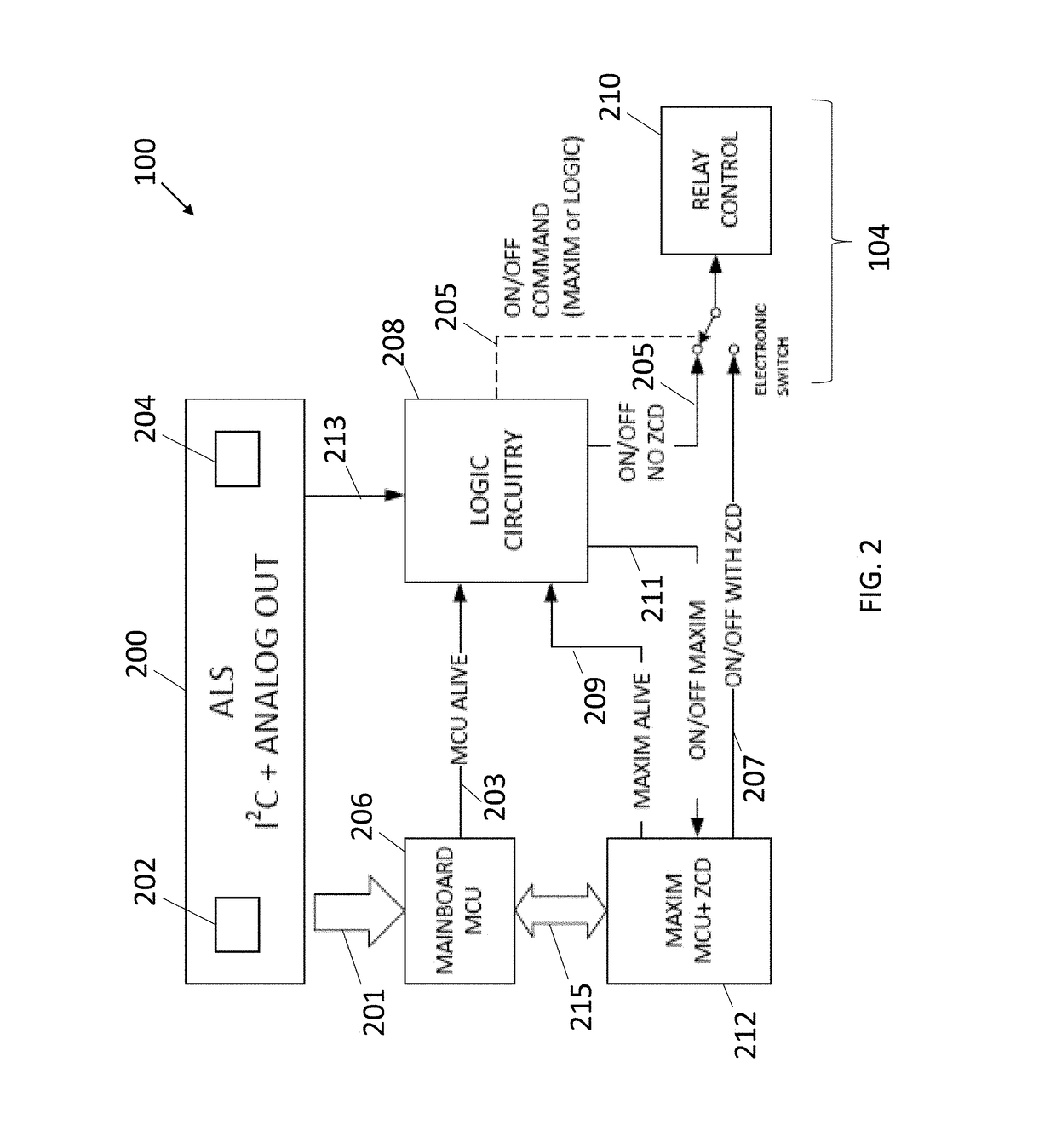
The patent text describes a networked light control system that includes light sensor circuitry, a control unit, and relay logic circuitry. The system uses the light sensors to sense the ambient light level and the control unit to generate a control signal to activate or deactivate the lights based on that level. The relay logic circuitry then controls the relays or solid state switches to activate or deactivate the lights accordingly. This system allows for automated control of the lights based on the ambient light levels, with the added benefit of being able to control the lights even in the event of a failure in the control unit.

Problems solved by technology

One problem with these systems and controllers can include the inability to turn off networked lights after a failure of the controller or other hardware circuitry in the system.
For example, the software running on the controller can crash (e.g., stop working as intended for at least a temporary time period) and prevent the controller from turning off one or more lights during daylight hours.
This can result in the consumption of energy to power the lights that is not needed or desired.

Method used


Image

  • Networked light control system and method
  • Networked light control system and method
  • Networked light control system and method

Examples


Embodiment Construction

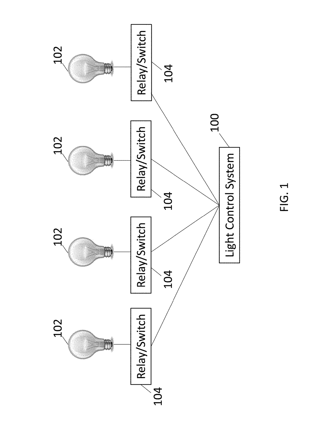
[0010]FIG. 1 illustrates one embodiment of a networked light control system 100. The system 100 is coupled with one or more lights 102 by switching devices 104 (“Relay / Switch” in FIG. 1). The system 100 can be coupled with the switching devices 104 via wired and / or wireless connections. The lights 102 are networked together by the system 100 such that the system 100 can remotely control activation or deactivation of the lights 102 at different locations. For example, the lights 102 may be disposed in different rooms, different floors of the same building, in different buildings, on different streets, in different towns, or the like. The system 100 can individually control which lights 102 are on or off by generating and communicating control signals to the switching devices 104. The switching devices 104 can open to deactivate an associated light 102 (e.g., by disconnecting the light 102 from a power source) and can close to activate the light 102 (e.g., by connecting the light 102 ...


PUM


Abstract

A networked light control system includes light sensor circuitry that includes plural light sensors configured to sense an ambient light level, a control unit configured to generate a control signal that activates or deactivates one or more lights in a network of lights based on the ambient light level that is sensed by the light sensor circuitry, and relay logic circuitry configured to open or close a relay or a solid state switch for activating or deactivating the one or more lights based on receipt of the control signal generated by the control unit. The relay logic circuitry is configured to control the relay or the solid-state switch responsive to a failure in the control unit.

Description

BACKGROUND[0001]Smart lighting systems include lights disposed in several locations and coupled with one or more smart controllers in a lighting network. The controllers can control which lights are on or off at different times and / or under various light conditions. For example, some light controllers may turn off a light responsive to an ambient light at or near the light rising above a threshold level and / or may turn the light on responsive to the ambient light at or near the light falling below the same threshold or a different threshold. This can allow for lights to automatically turn on at dusk or night and automatically turn off at sunrise or during daylight.[0002]One problem with these systems and controllers can include the inability to turn off networked lights after a failure of the controller or other hardware circuitry in the system. For example, the software running on the controller can crash (e.g., stop working as intended for at least a temporary time period) and pre...

Claims


Application Information

Patent Timeline
Patent Type & Authority Patents(United States)
IPC IPC(8): H05B37/02H05B33/08H05B44/00
CPCH05B37/0218H05B33/0854H05B47/11Y02B20/40H05B45/12
Inventor AMMARI, MOHAMMEDCHAOUA, YOUCEFBACON, LOUIS
Owner GE LIGHTING SOLUTIONS LLC
Learn More