
Verification-processing device, logic-generating device, and verification-processing method

a logic-generating device and verification-processing technology, applied in the direction of short-circuit testing, computer aided design, instruments, etc., can solve problems such as difficulty in verification, and achieve the effect of verifying safety

Active Publication Date: 2020-12-10
MITSUBISHI HEAVY IND ENG LTD
View PDF0 Cites 1 Cited by
  • Summary
  • Abstract
  • Description
  • Claims
  • Application Information

AI Technical Summary

Benefits of technology

The described device and method allow for verifying the safety of a relay logic circuit when a failure occurs. This is helpful in ensuring the reliable and safe operation of the device.

Problems solved by technology

However, it may be difficult to perform the verification in the case of occurrence of a failure such as unintentional contact with a connection line or the like in the relay logic circuit or a failure of an element forming the circuit, because there are many events to be assumed.

Method used


Image

  • Verification-processing device, logic-generating device, and verification-processing method
  • Verification-processing device, logic-generating device, and verification-processing method
  • Verification-processing device, logic-generating device, and verification-processing method

Examples


first embodiment

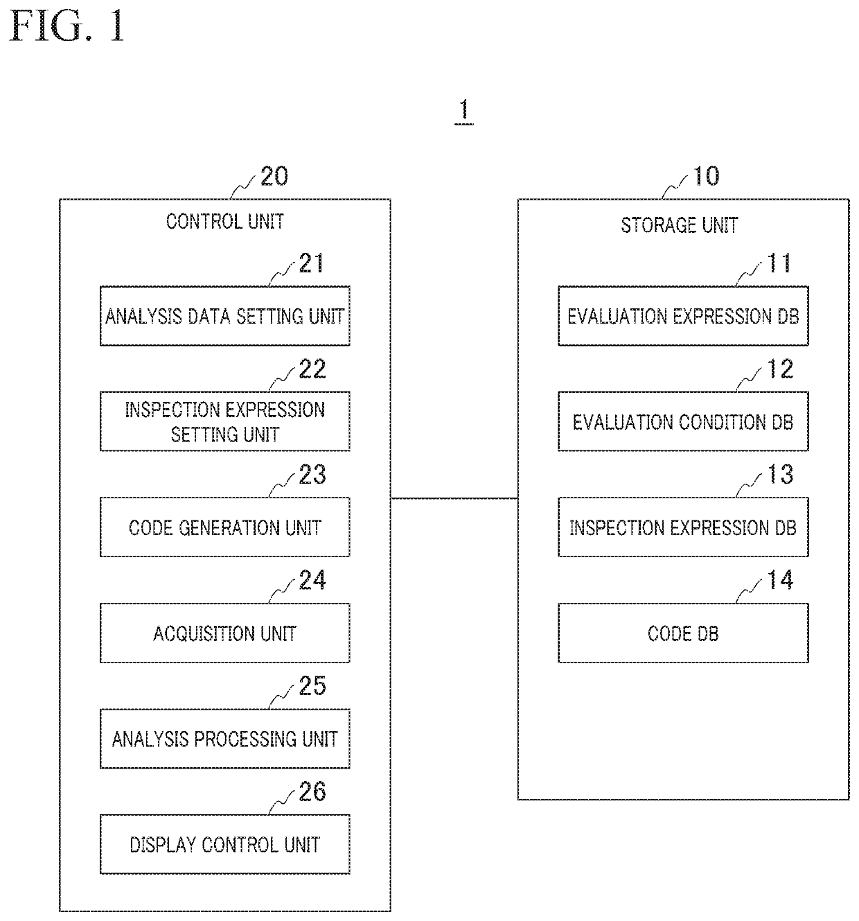
[0045]FIG. 1 is a configuration diagram showing a schematic configuration of a verification-processing device of the present embodiment.

[0046]As illustrated in FIG. 1, the verification-processing device 1 according to the present embodiment includes a storage unit 10 and a control unit 20.

[0047]The storage unit 10 stores data regarding the evaluation expression DB 11, the evaluation condition DB 12, the inspection expression DB 13, and the code DB 14.

[0048]The evaluation expression DB 11 includes data regarding the evaluation expression for the relay logic circuit to be evaluated. The evaluation expression is formed as a logical expression in which the relay, the element, and the connection line forming the relay logic circuit to be verified are variables. This evaluation expression includes at least a logical expression when a failure event occurs in the relay logic circuit. For example, the logical expression is generated for each relay whose operation is to be analyzed.

[0049]The ...

second embodiment

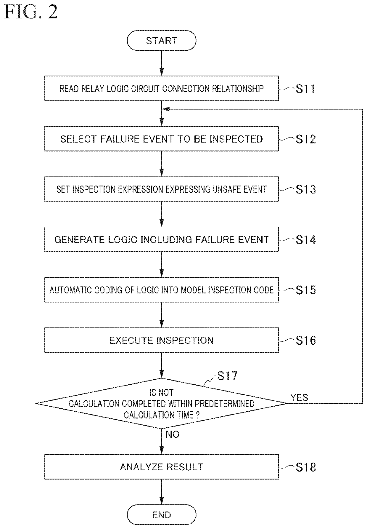
[0124]Subsequently, a second embodiment will be described with reference to drawings of FIG. 2 and FIGS. 6 to 15. Although the logic verification code as the model for logic verification is generated by the user in the first embodiment, the logic verification code of the present embodiment is generated by the verification-processing device.

[0125]FIG. 6 is a configuration diagram showing a schematic configuration of a verification-processing device of the present embodiment.

[0126]As illustrated in FIG. 6, the verification-processing device 1A according to the present embodiment includes a storage unit 10A and a control unit 20A.

[0127]The storage unit 10A includes an evaluation expression DB 11, an evaluation condition DB 12, an inspection expression DB 13, a code DB 14, an element information DB 15, and a signal information DB 16.

[0128]The element information DB 15 (Dev table) includes data of configuration information regarding the elements included in the relay logic circuit subjec...


PUM


Abstract

The verification-processing device includes an acquisition unit that is configured to acquire a circuit logic model represented by an evaluation expression represented by a logical expression taking as variables, a relay, an element, and a connection line that form a relay logic circuit to be verified, the evaluation expression including at least a logical expression for a case where a failure event occurs in the relay logic circuit; and a determination unit that is configured to determine the logical state of an output of the relay when a failure event occurs in the element or the connection line, based on the circuit logic model.

Description

[0001]Priority is claimed on Japanese Patent Application No. 2018-005995, filed on Jan. 17, 2018, the content of which is incorporated herein by reference.TECHNICAL FIELD[0002]The present invention relates to a verification-processing device, a logic-generating device, and a verification-processing method.BACKGROUND ART[0003]In the related art, relay logic circuits using relays have been used in various control systems. The verification of the basic operation of the relay logic circuit is performed by a verification-processing device such as a circuit simulator, and the reliability of its logical operation is ensured. However, it may be difficult to perform the verification in the case of occurrence of a failure such as unintentional contact with a connection line or the like in the relay logic circuit or a failure of an element forming the circuit, because there are many events to be assumed.[0004]Patent Literature 1 describes that a formal method typified by a model inspection met...

Claims


Application Information

Patent Timeline
IPC IPC(8): G06F30/3308
CPCG06F30/3308G06F2119/02G01R31/317G01R31/52
Inventor TAKAO, KENJIHIRAYAMA, KEITAYANAI, NORITAKA
Owner MITSUBISHI HEAVY IND ENG LTD
Learn More