Travelling vehicle system

a technology for traveling vehicles and vehicles, applied in the direction of transportation and packaging, interlocking arrangments of points, roads, etc., can solve the problems of limit of achieve the effect of improving the flexibility in the design of the track and enhancing the safety of the travelling vehicl

Active Publication Date: 2018-01-30
MURATA MASCH LTD
View PDF10 Cites 0 Cited by
  • Summary
  • Abstract
  • Description
  • Claims
  • Application Information

AI Technical Summary

Benefits of technology

[0011]In the travelling vehicle system with the above configuration, the travelling vehicle does not determine whether or not to be able to enter the switching track with respect to each switching track, but determines whether or not to be able to enter a plurality of switching tracks before entering the first switching track. Hence in the travelling vehicle system with the above configuration, the travelling vehicle does not need to wait before the switching track other than the first switching track with respect to each switching track in order to determine whether or not to be able to enter the switching track. Hence a place for making the travelling vehicle wait does not necessarily need to be provided between two adjacent switching tracks, thereby allowing improvement in flexibility in design of the track.
[0012]Moreover, in the travelling vehicle system with the above configuration, since the travelling vehicle determines whether or not to be able to enter the plurality of switching tracks before entering the first switching track, the travelling vehicle does not need to stop with respect to each switching track, thereby allowing smooth travelling.
[0016]In the travelling vehicle system with the above configuration, since the host controller waits for completion reports from a plurality of switching tracks and then issues an entry permission, the travelling vehicle can more safely travel the switching track.
[0022]In the travelling vehicle system with the above configuration, since the host controller waits for completion reports from a plurality of switching tracks and then issues an entry permission, the travelling vehicle can more safely travel the switching track.
[0024]In the travelling vehicle system with the above configuration, since there is included the report part which reports the state of the switching track when the travelling vehicle is travelling on the switching track, it is possible to further enhance the safety of the travelling vehicle.
[0025]According to the present invention, it is possible to improve the flexibility in design of the track in the travelling vehicle system.

Problems solved by technology

However, in the case of waiting before the switching track, a space for allowing the travelling vehicle to wait is required before the switching track.
In this case, there is a problem of limitations on flexibility in design of the track.

Method used


Image

  • Travelling vehicle system
  • Travelling vehicle system
  • Travelling vehicle system

Examples


embodiment 1

4-1. Alternative Embodiment 1

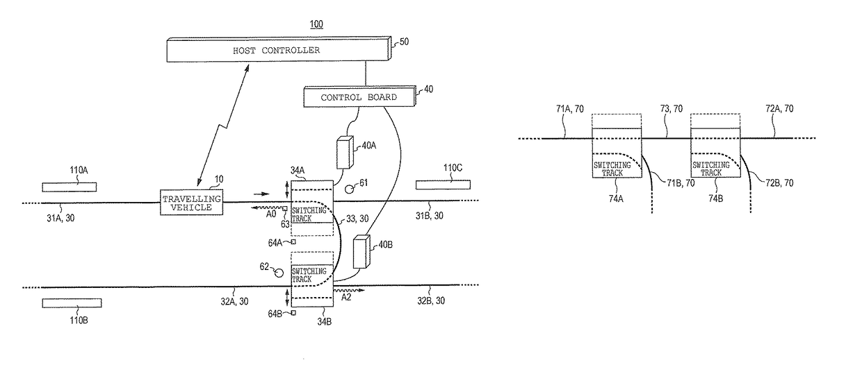
[0131]FIG. 6 is a view illustrating one example of a configuration of a track in a first alternative embodiment.

[0132]A track 70 includes an intermediate track 73, first tracks 71A and 71B and second tracks 72A and 72B, and is configured of a rail provided on a ceiling.

[0133]The first tracks 71A and 71B and the intermediate track 73 are connected to a switching track 74A. The second tracks 72A and 72B and the intermediate track are connected to a switching track 74B.

[0134]The switching tracks 74A and 74B are switching tracks each provided in a branching part of the track.

[0135]The switching track 74A couples the first track 71A to the first track 71B or the intermediate track 73. The switching track 74B couples the intermediate track 73 to the second track 72A or 72B.

[0136]It is to be noted that in the present alternative embodiment, for example when the route search part 15a of the travelling vehicle controller 15 selects the first track 71A, the interm...

second alternative embodiment

4-2. Second Alternative Embodiment

[0138]FIG. 7 is a view illustrating one example of a configuration of a track in a second alternative embodiment.

[0139]A track 80 includes an intermediate track 83, first tracks 81A and 81B and second tracks 82A and 82B, and is configured of a rail provided on a ceiling.

[0140]The first tracks 81A and 81B and the intermediate track 83 are connected to the switching track 84A. The second tracks 82A and 82B and the intermediate track are connected to the switching track 84B.

[0141]The switching tracks 84A and 84B are switching tracks each provided in a merging part of the track.

[0142]The switching track 84A couples the first track 81A or 81B to the intermediate track 83. The switching track 84B couples the intermediate track 83 or the second track 82A to the second track 82B.

[0143]It is to be noted that in the present alternative embodiment, for example when the route search part 15a of the travelling vehicle controller 15 selects the first track 81A, t...

third alternative embodiment

4. Third Alternative Embodiment

[0145]FIG. 8 is a view illustrating one example of a configuration of a track in a third alternative embodiment.

[0146]A track 90 includes an intermediate track 93, first tracks 91A and 91B and second tracks 92A and 92B, and is configured of a rail provided on a ceiling.

[0147]The first tracks 91A and 91B and the intermediate track 93 are connected to the switching track 94A. The second tracks 92A and 92B and the intermediate track are connected to the switching track 94B.

[0148]The switching track 94A is a switching track provided in a merging part of the track, and the switching track 94B is a switching track provided in a branching part of the track.

[0149]The switching track 94A couples the first track 91A or 91B to the intermediate track 93. The switching track 94B couples the intermediate track 93 to the second track 92A or 92B.

[0150]It is to be noted that in the present alternative embodiment, for example when the route search part 15a of the travel...


PUM


Abstract

A travelling vehicle system includes an intermediate track; first tracks; second tracks; a first switching track which connects the intermediate track and one of the first tracks to an other one track; and a second switching track which connects the intermediate track and one of the second tracks to the other one track. When a travelling vehicle travels on the intermediate track, a travelling vehicle controller determines before the travelling vehicle enters the first switching track that the travelling vehicle can enter both the first and second switching tracks in the case of determining that the first track on which the travelling vehicle is currently travelling is connected to the intermediate track and determining that the intermediate track is connected to the second track selected by the travelling vehicle.

Description

CROSS-REFERENCE TO RELATED APPLICATIONS[0001]This application claims the benefit of priority under 35 USC 119 of Japanese application no. 2014-178399, filed on Sep. 2, 2014, which is incorporated herein by reference.BACKGROUND OF THE INVENTION[0002]1. Field of the Invention[0003]The present invention relates to a travelling vehicle system for carrying a cargo along a track to transfer the cargo to a rack or the like.[0004]2. Description of the Related Art[0005]There has hitherto been known a travelling vehicle system for allowing a travelling vehicle to travel along a track hung on a ceiling to carry a cargo in the vicinity of the ceiling. The travelling vehicle is provided with a lift stage liftably hung by means of a hanging member. The travelling vehicle transfers the cargo by lowering the lift stage to a placement member of a rack arranged along a travelling route of the travelling vehicle.[0006]The track is installed in accordance with arrangement of the rack. The travelling ro...

Claims


Application Information

Patent Timeline
Patent Type & Authority Patents(United States)
IPC IPC(8): E01B25/12B61L23/34B61L27/00G06Q10/08B61L19/06B61L15/00B61B3/00
CPCE01B25/12B61B3/00B61L15/0027G06Q10/08B61L23/34B61L27/0038B61L19/06B61L27/20
Inventor KOUMOTO, HOMARE
Owner MURATA MASCH LTD
Why Eureka
Try Eureka