Image pickup device and method

a pickup device and image technology, applied in the direction of fluorescence/phosphorescence, radio control devices, instruments, etc., can solve the problems of image blurring, damage to the detection surface, and problems such as the protection of two-dimensional detection units, and achieve blurred image detection by two-dimensional detection units

Active Publication Date: 2018-01-30
FUJIFILM CORP
View PDF10 Cites 0 Cited by
  • Summary
  • Abstract
  • Description
  • Claims
  • Application Information

AI Technical Summary

Benefits of technology

[0010]As a method of locating the observation target and the two-dimensional detection unit away from each other and preventing blurring of an image detected by the two-dimensional detection unit, for example, providing an imaging optical system, such as a lens array in which fiber optics or refractive index distribution type lenses are arranged, between the observation target and the two-dimensional detection unit can be considered.
[0011]However, since fiber optics are so expensive, there is a problem that the cost is increased. In contrast, a lens array in which refractive index distribution type lenses are arranged is not as expensive as fiber optics. Accordingly, the influence of cost increase is small.
[0015]In view of the aforementioned problem, it is an object of the invention to provide an image pickup device and method capable of detecting light emitted from the area of an observation target corresponding to lens holding units and of capturing an appropriate image without image blurring.
[0028]In the image pickup device of the invention described above, the excitation light emission unit may stop emission of the excitation light during movement of the lens unit or the observation target holding unit and the detection unit.
[0031]In addition, the second position is set to a position when the lens array of the lens unit after the movement is disposed at a position facing the detection surface of the detection unit shielded by the lens holding unit when the lens unit is disposed at the first position. Therefore, since it is also possible to detect light emitted from the area of the observation target corresponding to the lens holding unit, it is possible to capture an appropriate image without image blurring.

Problems solved by technology

However, in the case of using a two-dimensional detection unit as described above, protection of the two-dimensional detection unit and blurring of an image become problems.
Specifically, for example, in a case where an observation target is directly placed on the detection surface of the two-dimensional detection unit and light emitted from the observation target is detected, there is a risk that the detection surface will be damaged by contact between the detection surface of the two-dimensional detection unit and the observation target.
Accordingly, there is a problem that an image detected by the two-dimensional detection unit is blurred.
However, since fiber optics are so expensive, there is a problem that the cost is increased.

Method used


Image

  • Image pickup device and method
  • Image pickup device and method
  • Image pickup device and method

Examples


Embodiment Construction

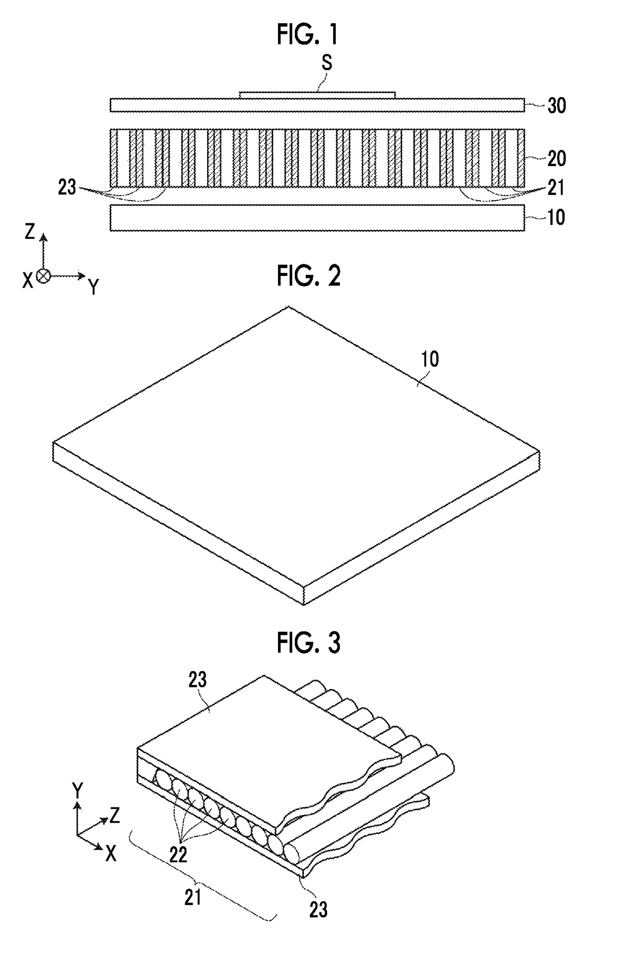
[0046]Hereinafter, an image pickup system using an embodiment of an image pickup device and method of the invention will be described in detail with reference to the accompanying diagrams. The image pickup system of the present embodiment includes an image pickup device main body and an image pickup control device that controls the image pickup device main body. FIG. 1 is a diagram showing the schematic configuration of the image pickup device main body in the image pickup system of the present embodiment.

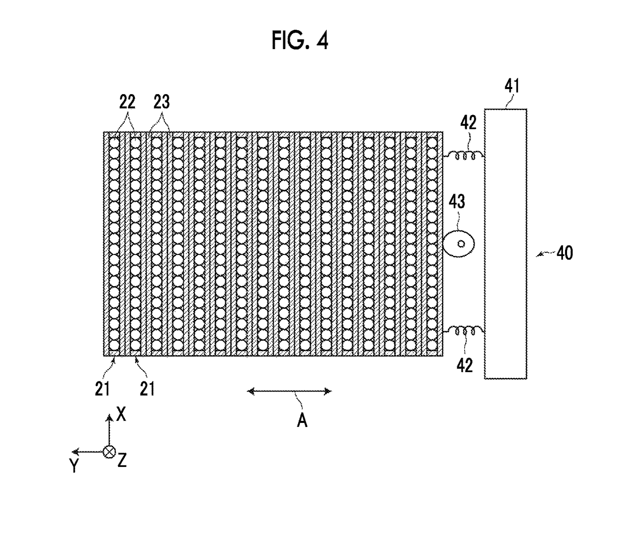
[0047]As shown in FIG. 1, the image pickup device main body of the present embodiment includes a detection unit 10, a lens unit 20, and an observation target holding unit 30. In the present embodiment, the image pickup device of the invention is formed by the detection unit 10, the lens unit 20, and the observation target holding unit 30 shown in FIG. 1, a moving mechanism 40 shown in FIG. 4, and a moving mechanism control unit 52 shown in FIG. 7.

[0048]The observation target holdin...


PUM

PropertyMeasurementUnit
sizeaaaaaaaaaa
diameteraaaaaaaaaa
refractive index distributionaaaaaaaaaa

Abstract

In an image pickup device and method using a lens unit in which a plurality of lens arrays, are arranged and a lens holding unit is provided between the lens arrays, light emitted from the area corresponding to the lens holding unit can be detected. A moving mechanism that moves a lens unit or the observation target holding unit and the detection unit, and a moving mechanism control unit are provided. The moving mechanism control unit controls the moving mechanism such that the lens unit or the observation target holding unit and the detection unit are moved to a second position from a first position. The second position is set to a position when the lens array after the movement is disposed at a position facing the detection surface of the detection unit shielded by a lens holding unit when the lens unit is disposed at the first position.

Description

CROSS-REFERENCE TO RELATED APPLICATIONS[0001]The present application claims priority under 35 U.S.C. § 119 to Japanese Patent Application No. 2015-136628, filed on Jul. 8, 2015. Each of the above application(s) is hereby expressly incorporated by reference, in its entirety, into the present application.BACKGROUND OF THE INVENTION[0002]1. Field of the Invention[0003]The present invention relates to an image pickup device and method for detecting light, which is emitted from an observation target held by an observation target holding unit, using a detection unit in which detection elements are arranged in a two-dimensional manner.[0004]2. Description of the Related Art[0005]In the related art, chemiluminescence or fluorescence emitted from an observation target is photoelectrically detected by detection elements, and an image is displayed based on the detection signal. As a method of detecting the chemiluminescence or fluorescence, for example, there is a method of scanning an observa...

Claims


Application Information

Patent Timeline
Patent Type & Authority Patents(United States)
IPC IPC(8): H04N5/357G02B3/06G02B3/00G01N21/76G01N21/64G02B26/08H01L27/146H04N1/19
CPCH04N5/3572G01N21/6456G01N21/76G02B3/005G02B3/06G02B26/0875G02B3/0062H04N1/19H01L27/14627
Inventor TANAKA, YASUTAKEISHIKAWA, HIROMIOHTA, YASUNORI
Owner FUJIFILM CORP
Why Eureka
Try Eureka