Eureka AIR delivers breakthrough ideas for toughest innovation challenges, trusted by R&D personnel around the world.

High-pressure waterjet cutting head systems, components and related methods

a cutting head and high-pressure waterjet technology, applied in the field of high-pressure waterjet cutting head systems, components, can solve the problems of insufficient cutting workpieces, abrasive system can suffer from other drawbacks, abrasive complexities, etc., to achieve the effect of reducing surface defects, preserving cutting performance, and adding functionality and processing flexibility

Active Publication Date: 2018-02-06
FLOW INT
View PDF81 Cites 7 Cited by
  • Summary
  • Abstract
  • Description
  • Claims
  • Application Information

AI Technical Summary

Benefits of technology

This patent describes high-pressure waterjet systems, cutting heads, and other components that are designed to cut composite materials accurately. The components are compact and efficient, with nozzle components that can clear obstacles like droplets and particles during cutting to prevent surface irregularities. The nozzle components can also alter the waterjet to reduce surface defects and detect and replace the orifice unit as its condition deteriorates. The patent also mentions that the components can be used in both pure waterjet cutting and abrasive waterjet cutting configurations, providing flexibility for different processing needs.

Problems solved by technology

Abrasive waterjet cutting systems are advantageously used when cutting workpieces made of carbon fiber reinforced plastic or other composite materials to meet exacting standards; however, the use of abrasives introduces complexities and abrasive systems can suffer from other drawbacks, including containment and management of spent abrasives.
Although pure waterjet systems may solve some of the drawbacks and avoid some of the complexities of abrasive waterjet systems, known systems that use pure waterjets unladen with abrasives are generally insufficient for cutting workpieces made of carbon fiber reinforced plastic or other similar composite materials to exacting standards.

Method used


Image

  • High-pressure waterjet cutting head systems, components and related methods
  • High-pressure waterjet cutting head systems, components and related methods
  • High-pressure waterjet cutting head systems, components and related methods

Examples


Embodiment Construction

[0026]In the following description, certain specific details are set forth in order to provide a thorough understanding of various disclosed embodiments. However, one of ordinary skill in the relevant art will recognize that embodiments may be practiced without one or more of these specific details. In other instances, well-known structures associated with waterjet cutting systems and methods of operating the same may not be shown or described in detail to avoid unnecessarily obscuring descriptions of the embodiments. For instance, it will be appreciated by those of ordinary skill in the relevant art that an abrasive source may be provided to feed abrasives to a cutting head assembly of the waterjet systems described herein to facilitate, for example, high-pressure abrasive waterjet cutting or processing of workpieces and work surfaces. As another example, well know control systems and drive components may be integrated into the waterjet systems to facilitate movement of the waterje...


PUM

PropertyMeasurementUnit
pressureaaaaaaaaaa
operating pressureaaaaaaaaaa

Abstract

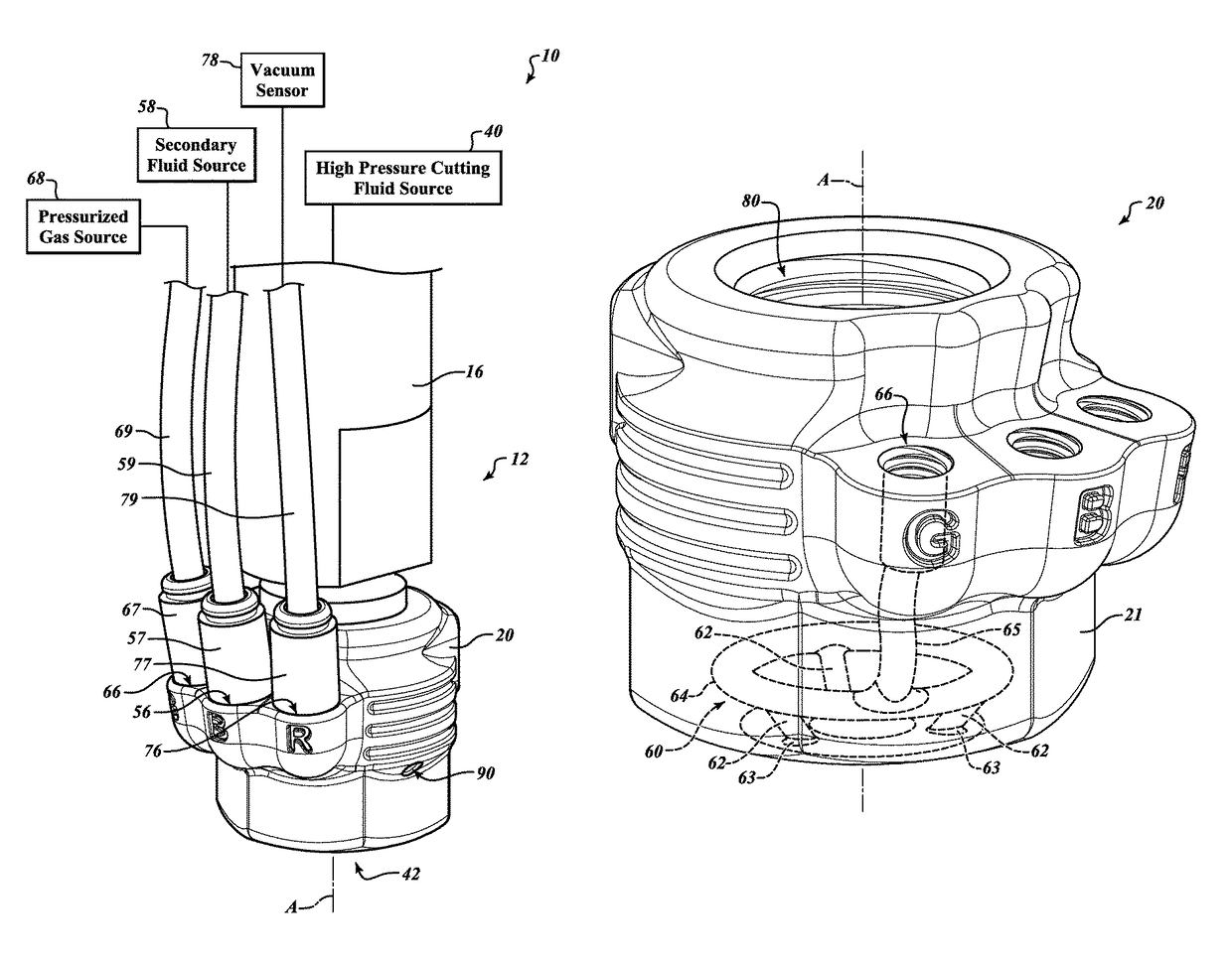
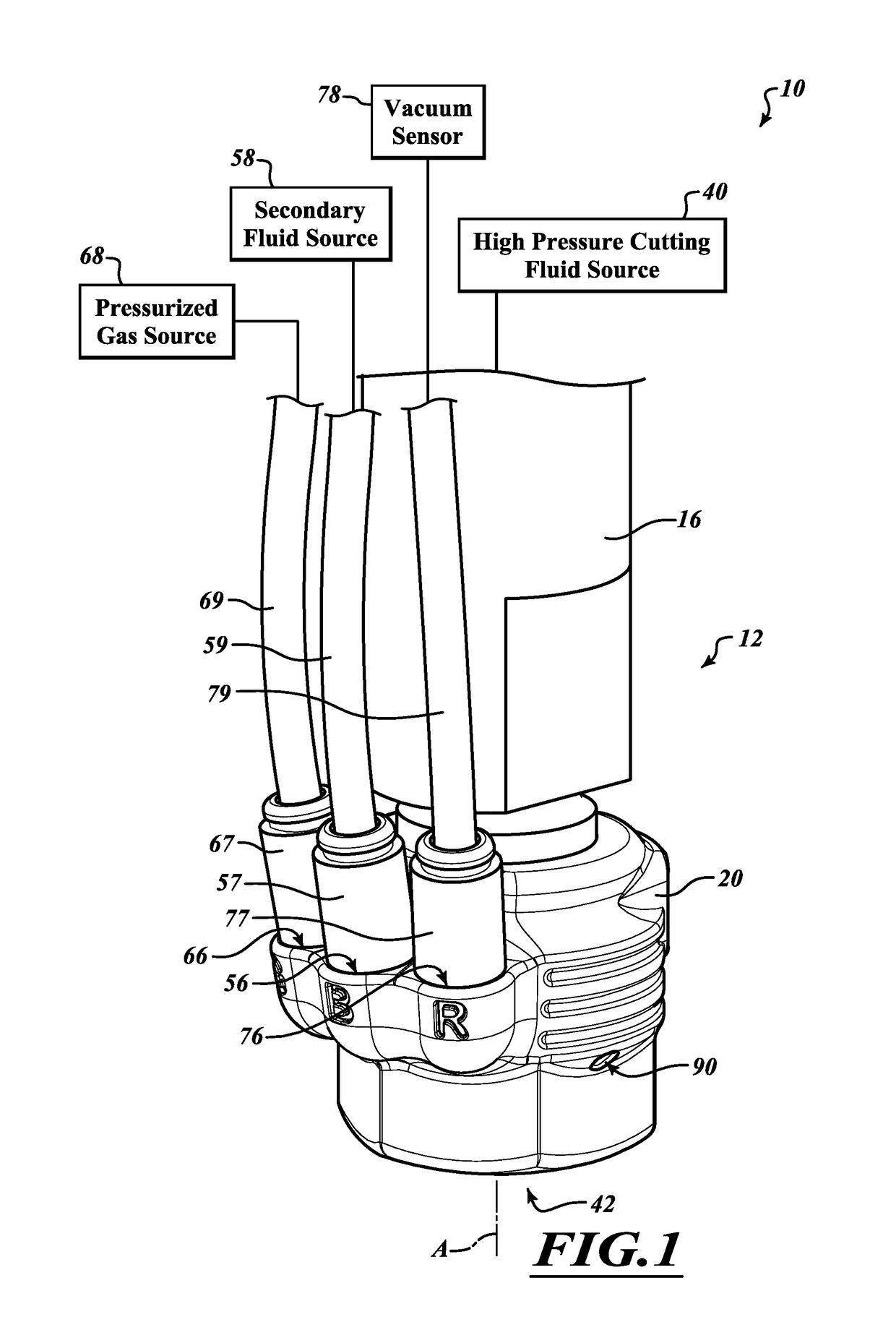
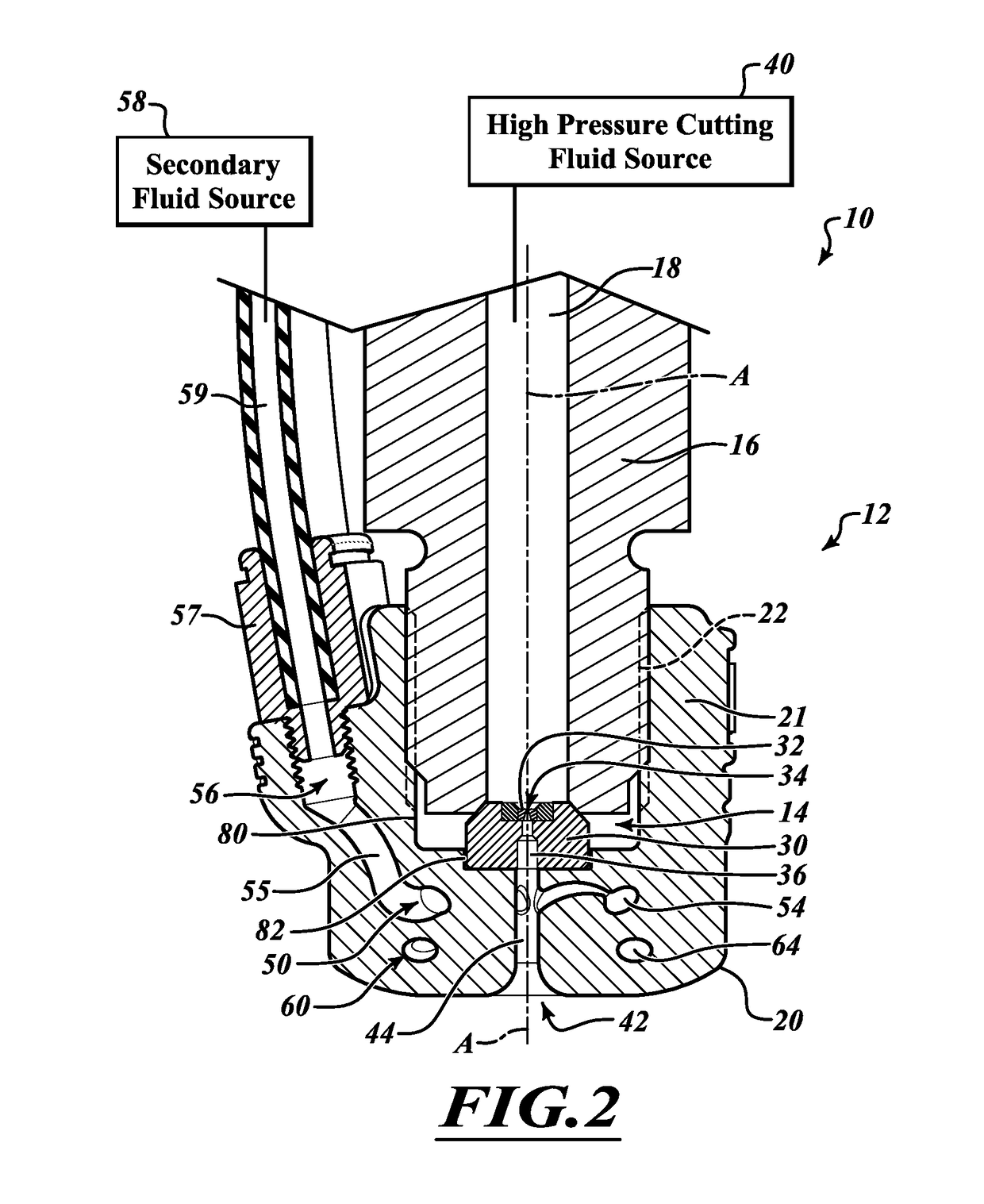
A waterjet cutting head assembly is provided which includes an orifice unit to generate a high-pressure waterjet, a nozzle body and a nozzle component coupled to the nozzle body with the orifice unit positioned therebetween. The nozzle component may include a waterjet passage, at least one jet alteration passage and at least one environment control passage. The jet alteration passage may intersect with the waterjet passage to enable selective alteration of the waterjet during operation via the introduction of a secondary fluid or application of a vacuum. The environment control passage may include one or more downstream portions aligned relative to the fluid jet passage so that gas passed through the environment control passage during operation is directed to impinge on an exposed surface of a workpiece at or adjacent to a location where the waterjet is cutting the workpiece. Other high-pressure waterjet cutting systems, components and related methods are also provided.

Description

BACKGROUND[0001]Technical Field[0002]This disclosure is related to high-pressure waterjet cutting systems, components thereof and related methods, and, in particular, to nozzle components of high-pressure waterjet cutting heads and related methods that are well suited for cutting workpieces with high precision using a pure waterjet or abrasive waterjet.[0003]Description of the Related Art[0004]Waterjet or abrasive waterjet systems are used for cutting a wide variety of materials, including stone, glass, ceramics and metals. In a typical waterjet system, high-pressure water flows through a cutting head having a nozzle which directs a cutting jet onto a workpiece. The system may draw or feed abrasive media into the high-pressure waterjet to form a high-pressure abrasive waterjet. The cutting head may then be controllably moved across the workpiece to cut the workpiece as desired, or the workpiece may be controllably moved beneath the waterjet or abrasive waterjet. Systems for generati...

Claims


Application Information

Patent Timeline
Patent Type & Authority Patents(United States)
IPC IPC(8): B24C5/04B24C5/02B24C1/04B26F3/00B24C7/00
CPCB24C5/04B24C1/045B24C5/02B24C7/0007B24C7/0076B24C7/0084B26F3/004B24C7/0046Y10T83/0591B24C3/02B24C9/00B24C7/00B26F2003/006
Inventor HASHISH, MOHAMED A.CRAIGEN, STEVEN J.SCHUMAN, BRUCE M.
Owner FLOW INT
Why Eureka
Eureka Blog
Learn More