Vibration damper device and load-bearing wall structure

a technology of vibration damper and load bearing wall, which is applied in the direction of construction, building types, building components, etc., can solve the problems of small space for disposing viscoelastic dampers and difficulty in inclining each brace at a desired angle, so as to avoid interference with a main reinforcement, increase the number of fixation members, and increase the shear capacity

Active Publication Date: 2018-02-06
MITSUI HOME
View PDF10 Cites 5 Cited by
  • Summary
  • Abstract
  • Description
  • Claims
  • Application Information

AI Technical Summary

Benefits of technology

[0009]According to the present invention, each of the lower braces and the upper braces includes the recess which is formed by cutting out the end on the central vertical frame side of the brace so as to avoid interference with the central vertical frame. Thus, it is possible to bring the ends on the central vertical frame side of the respective braces closer to the central vertical frame as compared to the braces of Patent Document 1 each of which has the constant cross-sectional dimensions throughout its length. In this way, each brace can be arranged at a larger inclination angle with respect to the central vertical frame. As a consequence, stability of each brace is increased so that seismic force acting on the wall framework can be reliably transmitted to the viscoelastic dampers. In addition, according to the present invention, each of the lower braces and the upper braces includes a slit into which the corresponding connection member is inserted. Accordingly, interlock between the braces and the connection members is enhanced. As a consequence, the seismic force acting on the wall framework can be smoothly transmitted from the braces to the viscoelastic dampers even in the case of providing the recess.
[0011]In this way, the two sides in the wall width direction of each connection member are held in the slits. Accordingly, interlock between each brace and the corresponding connection member is further enhanced. As a consequence, the seismic force can be smoothly transmitted from the braces to the viscoelastic dampers.
[0013]In this way, each brace is formed into the flat hollow shape, which is longer in the wall width direction than in the wall thickness direction. This configuration enhances strength and rigidity of each brace in the wall width direction which is a direction of action of the seismic force. As a consequence, the seismic force can be smoothly transmitted from each brace to the corresponding viscoelastic damper.
[0015]In this way, each connection member can control an angular variation between the base plate and the brace, and the seismic force can be reliably transmitted to the corresponding viscoelastic damper. As a consequence, it is possible to increase an amount of shear deformation of each viscoelastic damper and thus to increase an amount of absorption of the seismic force.
[0017]According to the present invention, when the vibration damper device of the present invention is attached to a wall on a lower floor (such as a first floor), an operation to attach the base plates to the upper frame and the constructional material can take place on the wall on the lower floor. As a consequence, the installation operation can be conducted without destroying the members on an upper floor (such as a second floor) side, and installation workability is thus enhanced. Moreover, according to the present invention, when the vibration damper device of the present invention is attached to a wall on the upper floor (such as the second floor), an operation to attach the base plates to the lower frame and the constructional material can take place on the wall on the upper floor. As a consequence, the installation operation can be conducted without destroying the members on the lower floor (such as the first floor) side, and installation workability is thus enhanced.
[0019]According to the present invention, it is possible to drive in the fixation member while avoiding interference with a main reinforcement that is located at a relatively shallow position from an upper face of the base upright portion. Thus, it is possible to counter tensile force with a shear capacity of the fixation member. In addition, it is also possible to increase the shear capacity by increasing the number of the fixation members. Meanwhile, according to the present invention, it is only necessary to put the board plate in a portal shape and provided with the anchor unit on the lower constructional material from above. Accordingly, this configuration suppresses the cutting work on the lower constructional material and facilitates the installation operation.

Problems solved by technology

Nonetheless, there is only a small space for disposing the viscoelastic dampers.
Thus, it is difficult to incline each brace at a desired angle.

Method used


Image

  • Vibration damper device and load-bearing wall structure
  • Vibration damper device and load-bearing wall structure
  • Vibration damper device and load-bearing wall structure

Examples


Embodiment Construction

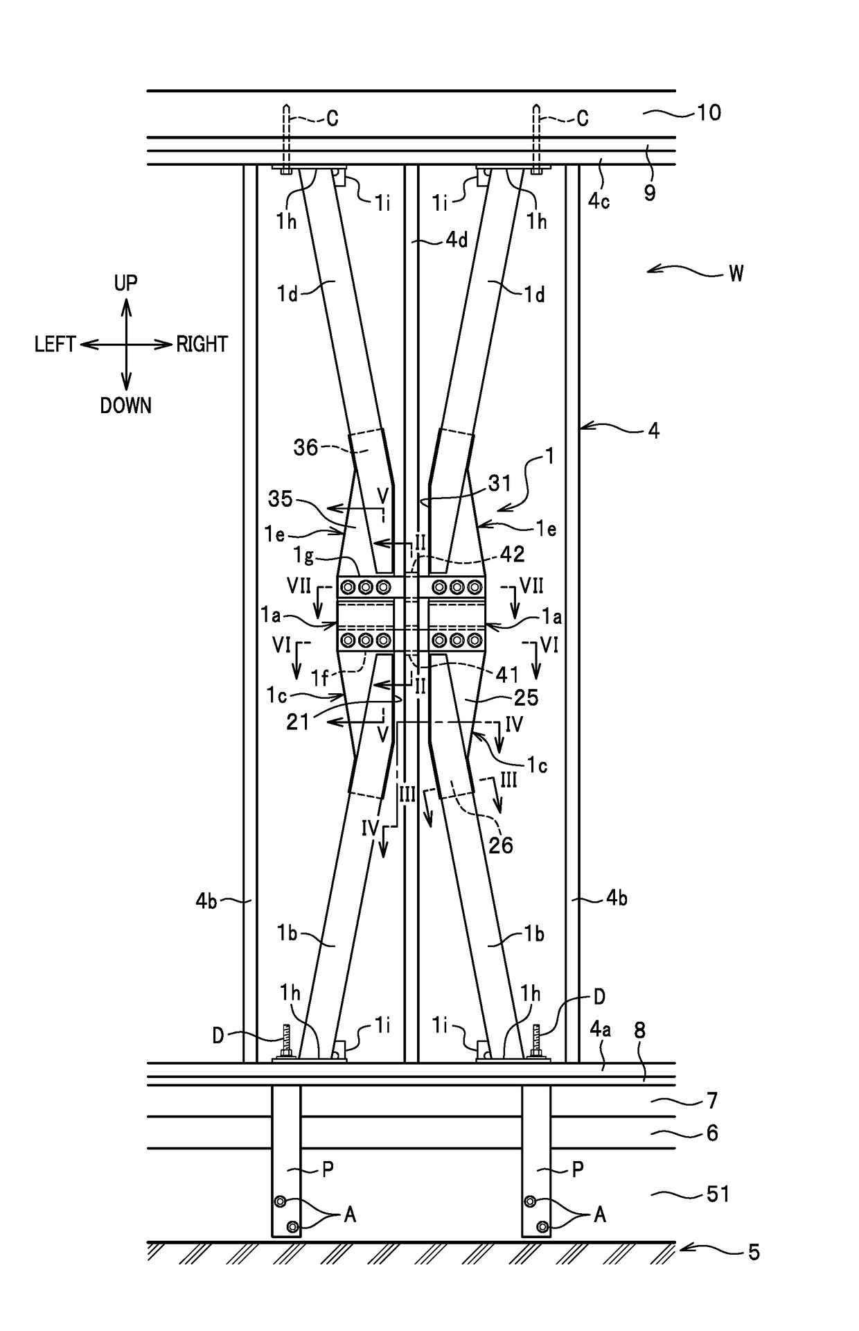
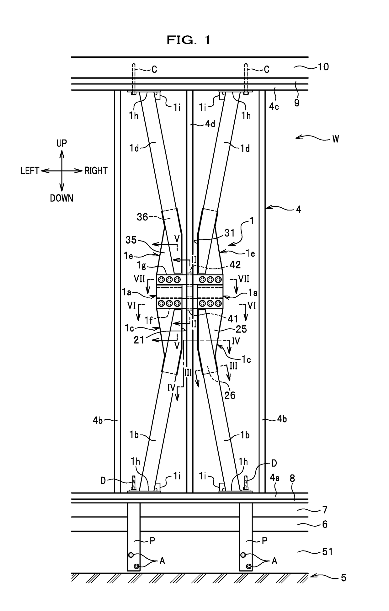
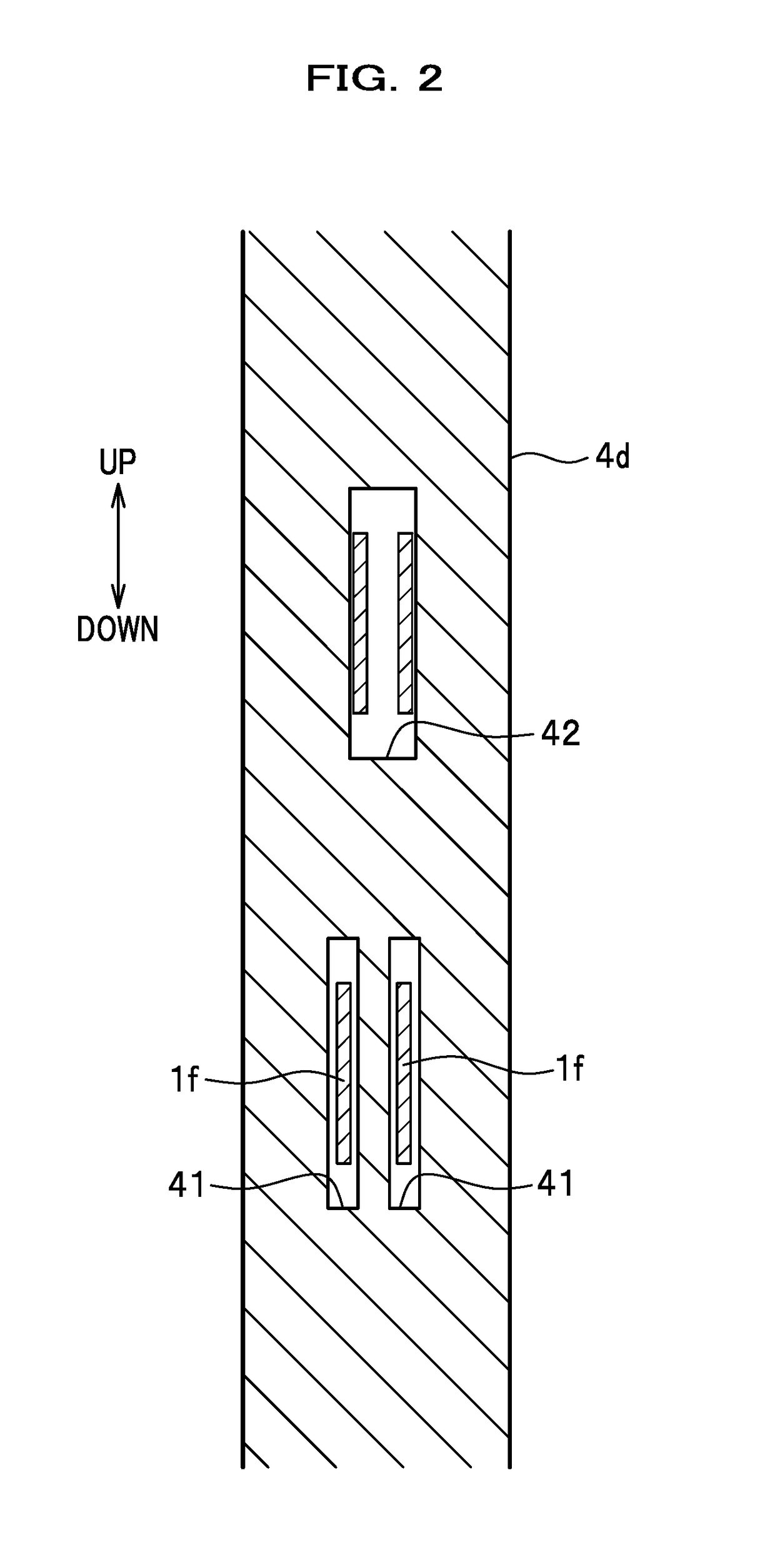
[0033]An embodiment of the present invention will be described in detail with reference to the accompanying drawings. In the description, the same constituents are denoted by the same reference signs and overlapping explanations will be omitted.

[0034]As shown in FIG. 1, a load-bearing wall structure W according to the embodiment of the present invention includes a base 5, a foundation 6 disposed on an upper face of the base 5, floor joists 7 disposed on an upper face of the foundation 6, and a floor structure plywood plate 8 disposed on upper faces of the floor joists 7. Moreover, the load-bearing wall structure W includes a wall framework 4 disposed on an upper face of the floor structure plywood plate 8, a vibration damper device 1 disposed inside the wall framework 4, a top plate 9 disposed on an upper face of the wall framework 4, and a floor beam 10 disposed on an upper face of the top plate 9. Note that although this embodiment explains an example of applying the load-bearing ...


PUM


Abstract

A vibration damper device includes a pair of viscoelastic dampers, lower braces which support the viscoelastic dampers from below, upper braces which support the viscoelastic dampers from above, lower connection members which connect the viscoelastic dampers to the lower braces, upper connection members which connect the viscoelastic dampers to the upper braces, and first joining members and second joining members which join the pair of viscoelastic dampers. Each lower brace includes a lower recess which avoids interference with the central vertical frame, and a lower slit into which the lower connection member is inserted. Each upper brace includes an upper recess which avoids interference with the central vertical frame, and an upper slit into which the upper connection member is inserted.

Description

BACKGROUND OF THE INVENTION1. Field of the Invention[0001]The present invention relates to a vibration damper device and a load-bearing wall structure provided with the vibration damper device.2. Description of the Related Art[0002]An invention to dispose a vibration damper device inside a wall framework is disclosed in Japanese Patent No. 5830477 (Patent Document 1), for example.[0003]The wall framework of Patent Document 1 is constructed by erecting three vertical frames at regular intervals between a lower frame and an upper frame. The vibration damper device of Patent Document 1 includes: a pair of viscoelastic dampers disposed while sandwiching the vertical frame located in the center (hereinafter referred to as a “central vertical frame”); a pair of lower braces supporting the viscoelastic dampers from below; a pair of upper braces supporting the viscoelastic dampers from above; and joining members each penetrating the central vertical frame in a wall width direction and joini...

Claims


Application Information

Patent Timeline
Patent Type & Authority Patents(United States)
IPC IPC(8): E04B1/98E04B1/26E04H9/02
CPCE04B1/98E04H9/021E04B1/26E04B2001/2696E04H9/0237
Inventor IZUMI, JUNICHIMATSUO, KAZUMA
Owner MITSUI HOME
Why Eureka
Try Eureka