Eureka AIR delivers breakthrough ideas for toughest innovation challenges, trusted by R&D personnel around the world.

Method and system for vacuum generation using a throttle body comprising a slidable throttle valve

a technology of vacuum generation and throttle body, which is applied in the direction of electric control, combustion air/fuel air treatment, machines/engines, etc., can solve the problems of limited vacuum generation increased related expenses, and additional expenses, so as to achieve limited vacuum generation potential of the throttle, the effect of limited vacuum generation potential and limited perforation siz

Inactive Publication Date: 2018-02-06
FORD GLOBAL TECH LLC
View PDF20 Cites 2 Cited by
  • Summary
  • Abstract
  • Description
  • Claims
  • Application Information

AI Technical Summary

Benefits of technology

[0004]However, as recognized by the inventors herein, in the approaches described above, the vacuum generation potential of the throttle may be limited. For example, a single control bore at one location in the intake, as shown in U.S. Pat. No. 8,261,716, is utilized by the vacuum consumption device even though vacuum may be generated at the entire periphery of the throttle. To use vacuum generated at the entire periphery of the throttle, more control bores may be needed in the intake passage. However, fabricating these control bores may result in significant modifications to the design of the intake passage which can increase related expenses.
[0007]The inventors herein have also identified potential issues with the above approach. As an example, the vacuum generation potential of the throttle is limited. As an example, the size of the perforations may be limited due to the width of the throttle valve, and therefore the vacuum generation potential of the throttle is limited. Thus, in order to increase the vacuum generated at the periphery of the throttle, the size of the perforations may need to be increased. However, increasing the size of the perforations may result in increases of the size and of the throttle which may result in significant modifications to the design of the intake passage which can increase related expenses.
[0011]In this way, a Venturi effect created between a throttle valve and a throttle fixture positioned in a throttle can be advantageously used to generate vacuum for a vacuum consumption device. The throttle valve may include a hollow interior passage that may be fluidically coupled to a vacuum consumption device for drawing air from the vacuum consumption device into the throttle. By adjusting the position, size, and / or shape of the throttle valve, the vacuum generation potential of the throttle valve may be increased. In addition, airflow into the intake manifold can be more accurately controlled by adjusting the distance between the throttle valve and the throttle fixture. Furthermore, since air received from the vacuum consumption device during vacuum application is received substantially at the throttle valve, airflow errors can be more accurately compensated for. By combining the functions of a throttle and an aspirator into a single throttle valve with a hollow interior passage, additional control valves, such as an ASOV, and parts may not be needed. By reducing the number and size of components required for vacuum generation, manufacturing expenses may be lowered and packaging issues may be averted.

Problems solved by technology

However, as recognized by the inventors herein, in the approaches described above, the vacuum generation potential of the throttle may be limited.
However, fabricating these control bores may result in significant modifications to the design of the intake passage which can increase related expenses.
In the approaches that use one or more aspirators to generate vacuum, additional expenses may be incurred because of individual parts that form the aspirator including nozzles, mixing and diffusion sections, and check valves.
Further, at idle or low load conditions, it may be difficult to control the total air flow rate into the intake manifold since the flow rate is a combination of leakage flow from the throttle and airflow from the aspirator.
Typically, an aspirator shut off valve (ASOV) may be included along with the aspirator to control airflow but with added cost.
Further, installing aspirators in the intake can lead to constraints on space availability as well as packaging issues.
As an example, the vacuum generation potential of the throttle is limited.
As an example, the size of the perforations may be limited due to the width of the throttle valve, and therefore the vacuum generation potential of the throttle is limited.
However, increasing the size of the perforations may result in increases of the size and of the throttle which may result in significant modifications to the design of the intake passage which can increase related expenses.

Method used


Image

  • Method and system for vacuum generation using a throttle body comprising a slidable throttle valve
  • Method and system for vacuum generation using a throttle body comprising a slidable throttle valve
  • Method and system for vacuum generation using a throttle body comprising a slidable throttle valve

Examples


embodiment 400

[0079]FIG. 4A shows an embodiment 400, where throttle valve 64 is in the open first position. Airflow through the throttle body 62 may be greater with the throttle valve 64 in the open first position than any other throttle position. Thus, the position of the throttle valve 64 shown in FIG. 4A may be referred to as a fully open position. Throttle valve 64 may not overlap with the flange 240. More precisely, a given cross-section of the throttle body 62 taken along the vertical axis 236, may not include both the flange 240 and throttle valve 64, when the throttle valve is adjusted to the open first position. Said another way, no portion of the throttle valve 64 may be positioned over any portion of the flange 240. However, in other examples, some overlap between the throttle valve 64 and the flange 240 may exist in the open first position. As such, a narrowing of the throttle body 62 may be less in the open first position, than more closed positions, and airflow through the throttle ...

embodiment 425

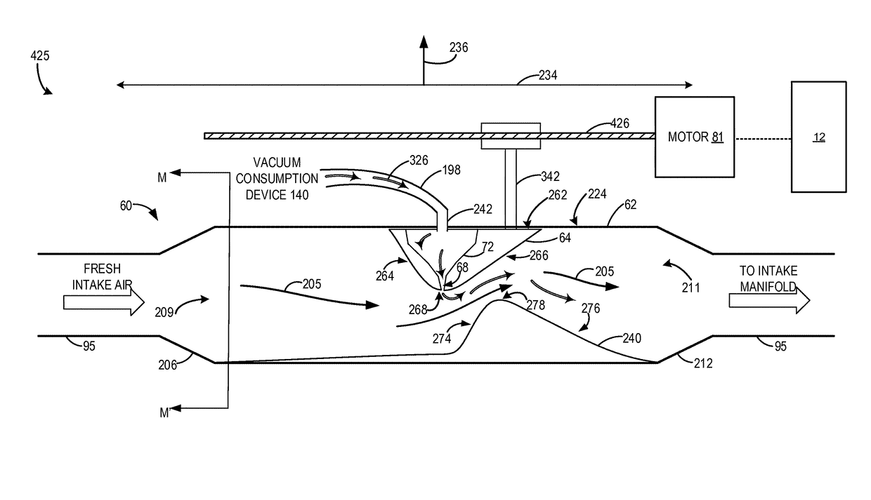
[0080]FIG. 4B shows an embodiment 425, where the throttle valve 64 is displaced downstream in the throttle body 62 along the longitudinal axis 234, relative to the open first position shown in FIG. 4A to an intermediate third position. As such airflow through the throttle body 62 may be less in the third position than in the open first position. However, an amount of vacuum generated at the tip 268 of the throttle valve 64 may be greater at the third position than the open first position. Thus, an amount of gasses drawn from the vacuum consumption device 140 into the throttle body 62 may be greater in the third position than the open first position as shown by the increased number of flow arrows 326 in FIG. 4B relative to FIG. 4A. In the intermediate third position, the throttle valve 64 may overlap with the flange 240. That is, a given cross-section of the throttle body 62 taken along the vertical axis 236, may include both the flange 240 and throttle valve 64, when the throttle va...

embodiment 450

[0081]FIG. 4C shows an embodiment 450, where the throttle valve 64 is displaced downstream in the throttle body 62 along the longitudinal axis 234, relative to the open first position and intermediate third position shown in FIGS. 4A and 4B, to the closed second position. As such airflow through the throttle body 62 may be less in the closed second position than in the open first position and intermediate third position. However, an amount of vacuum generated at the tip 268 of the throttle valve 64 may be greater at closed second position than the open first position and intermediate third position. Thus, an amount of gasses drawn from the vacuum consumption device 140 into the throttle body 62 may be greater in the closed second position than the open first position and intermediate third position as shown by the increased number of flow arrows 326 in FIG. 4C relative to FIGS. 4A and 4B.

[0082]In the closed second position, the throttle valve 64 may fully overlap with the flange 240...


PUM


Abstract

Various systems and methods are described for generating vacuum within an engine intake. A system may comprise an intake throttle including a slidable throttle valve, where the throttle valve may comprise a hollow interior passage, which in turn may be coupled to a vacuum consumption device. When vacuum is demanded by the vacuum consumption device, the throttle valve may be displaced downstream within the throttle to decrease airflow through the throttle and vacuum may be generated at tip of the throttle valve by flowing intake air between the throttle valve and a throttle fixture.

Description

TECHNICAL FIELD[0001]The present application relates to vacuum generation in an intake via a throttle valve.BACKGROUND AND SUMMARY[0002]Vehicle systems may include various vacuum consumption devices that are actuated using vacuum. These may include, for example, a brake booster and a purge canister. Vacuum used by these devices may be provided by a dedicated vacuum pump. In other embodiments, one or more aspirators (alternatively referred to as ejectors, venturi pumps, jet pumps, and eductors) may be coupled in the engine system that may harness engine airflow and use it to generate vacuum.[0003]In yet another example embodiment shown by Bergbauer et al. in U.S. Pat. No. 8,261,716, a control bore is located in the wall of the intake such that when the throttle valve is at idle position, vacuum generated at the periphery of the throttle is used for a vacuum consumption device. Therein, the positioning of the throttle valve in an idle position provides a constriction at the throttle v...

Claims


Application Information

Patent Timeline
Patent Type & Authority Patents(United States)
IPC IPC(8): F02D9/02F02D41/00F02D9/14F02D13/02F02D41/26F02M35/10F02D23/00
CPCF02D41/0002F02D9/14F02D13/0234F02D41/005F02D41/0077F02D41/26F02M35/10222F02M35/10229F02M35/10255F02D9/02F02D2250/41F02D23/00F02D41/0007F02D2009/024F02D2041/001F02D2041/0017F02D9/12F02D2041/0022Y02T10/40
Inventor ZHANG, XIAOGANG
Owner FORD GLOBAL TECH LLC
Why Eureka
Eureka Blog
Learn More