Display device having display cells capable of being independently driven

a display device and display panel technology, applied in the direction of instruments, static indicating devices, etc., can solve the problems of increasing power consumption and forming of display cells, and achieve the effects of reducing the intensity of light that passes through the display cell, reducing the luminance of an image, and increasing the intensity of light emitted

Active Publication Date: 2018-02-13
JAPAN DISPLAY INC
View PDF12 Cites 1 Cited by
  • Summary
  • Abstract
  • Description
  • Claims
  • Application Information

AI Technical Summary

Benefits of technology

[0006]In the related art, micro-processing of display cells has been necessary according to image definition enhancement, which causes problems in formation of the display cells. Further, since an opening area of a pixel is reduced according to the image definition enhancement, in a liquid crystal display device, the intensity of the light that passes through a display cell is reduced, and in an organic EL display device, a light emitting area of a display cell is reduced, both of which lead to reduction in the luminance of an image. By increasing the intensity of light emitted from a backlight, or by increasing power supplied to an organic light-emitting diode (OLED), it is possible to increase luminance and to obtain necessary brightness for displaying an image. However, this method causes an increase in power consumption.

Problems solved by technology

In the related art, micro-processing of display cells has been necessary according to image definition enhancement, which causes problems in formation of the display cells.
However, this method causes an increase in power consumption.

Method used


Image

  • Display device having display cells capable of being independently driven
  • Display device having display cells capable of being independently driven
  • Display device having display cells capable of being independently driven

Examples


first exemplary embodiment

[0057

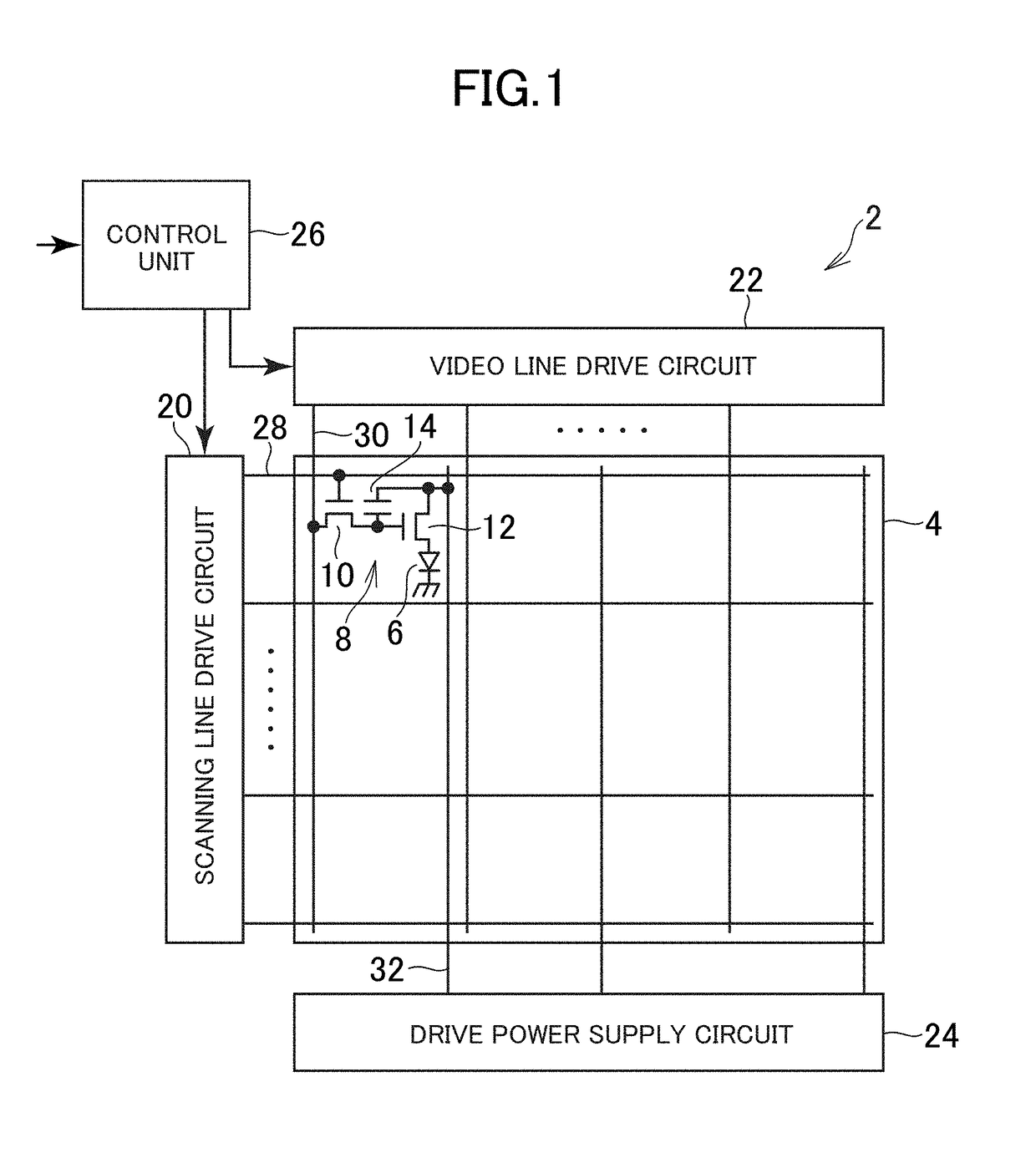
[0058]FIG. 1 is a schematic diagram illustrating a configuration of an outline of an organic EL display device 2 according to a first exemplary embodiment. The organic EL display device 2 includes a pixel array section 4 that displays an image, and a drive unit (drive circuit) that drives the pixel array. The organic EL display device 2 is a flat panel display, and includes a display panel, in which the pixel array section 4 is provided in the display panel.

[0059]Plural display cells are two-dimensionally arranged corresponding to plural pixels that form an image, in the pixel array section 4. The organic EL display device 2 may individually drive the plural display cells. In the present exemplary embodiment, the display cells are arranged in a matrix form. An OLED 6 and a pixel circuit 8 are provided in each display cell. The pixel circuit 8 includes plural TFTs 10 and 12 and a capacitor 14.

[0060]Additionally, the drive unit includes a scanning line drive circuit 20, a video l...

second exemplary embodiment

[0099

[0100]With respect to an organic EL display device 2 according to a second exemplary embodiment, the same reference numerals are given to the same components as in the first exemplary embodiment, and basic description thereof will not be repeated. Hereinafter, different points from the first exemplary embodiment will mainly be described.

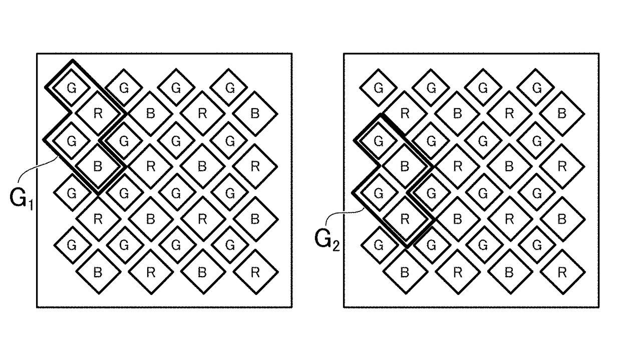
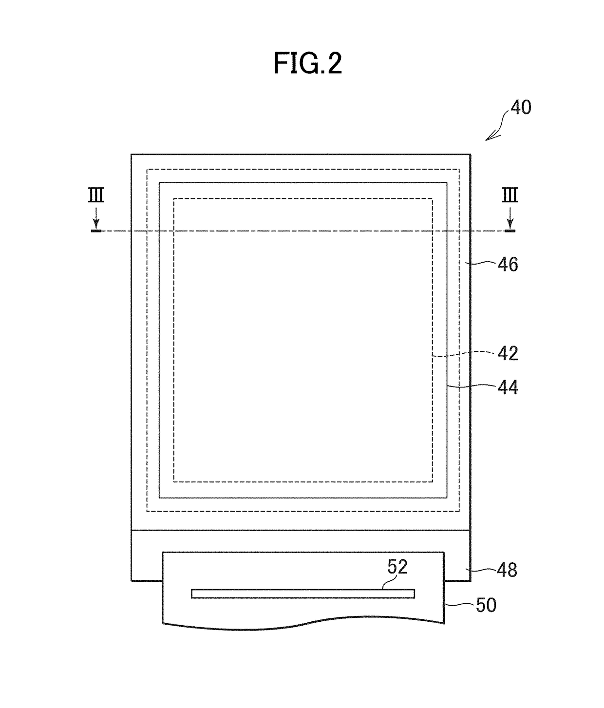
[0101]FIG. 12 is a schematic plan view of a pixel array section 4 according to the second exemplary embodiment, and shows an arrangement of plural types of display cells having different light emitting colors. A display panel 40 of the present exemplary embodiment has three types of display cells having different light emitting colors, which are arranged in a matrix form, in which a column in which a first type of display cell and a second type of display cell are alternately arranged in every cell and a column in which a third type of display cell is arranged in a stripe form are alternately arranged in a row direction, and the first type of di...

first modification example

[0106 of the Second Exemplary Embodiment

[0107]In the arrangement of the display cells shown in FIG. 12, each of the display cell groups G1 to G4 may be configured to include four display cells that are arranged in two rows and two columns, similar to the first exemplary embodiment. In this configuration, similar to the first exemplary embodiment, with respect to the display cell group G1(2n−1, 2m−1) corresponding to the pixels P(2n−1, 2m−1) of the first sub-sampling image 202a, the display cell group G2(2n, 2m−1) corresponding to the pixels P(2n, 2m−1) of the second sub-sampling image 202b is shifted by one cell in the column direction, the display cell group G3(2n, 2m) corresponding to the pixels P(2n, 2m) of the third sub-sampling image 202c is shifted by one cell in the column direction and the row direction, respectively, and the display cell group G4(2n−1, 2m) corresponding to the pixels P(2n−1, 2m) of the fourth sub-sampling image 202d is shifted by one cell in the row directi...


PUM


Abstract

Disclosed is a display device capable of achieving a high definition imaging without depending on micronization of display cells. The display device includes: a display panel in which display cells capable of being independently driven are two-dimensionally arranged; and a drive circuit that decomposes an original image that includes plural pixels into plural sub-sampling images that include the pixels which are respectively intermittent in a row direction and a column direction, and sequentially displays the plural sub-sampling images on the display panel. The drive circuit drives a display cell group including plural display cells that are two-dimensionally arranged to be adjacent to each other, corresponding to the respective pixels. The display cell groups respectively corresponding to two arbitrary sub-sampling images are overlapped and are disposed to be mutually shifted.

Description

CROSS-REFERENCE TO RELATED APPLICATION[0001]The present application claims priority from Japanese application JP2014-121885 filed on Jun. 12, 2014, the content of which is hereby incorporated by reference into this application.BACKGROUND OF THE INVENTION[0002]1. Field of the Invention[0003]The present invention relates to a display device having a display panel in which display cells capable of being independently driven are two-dimensionally arranged.[0004]2. Description of the Related Art[0005]A display device such as an organic electroluminescence (EL) display device or a liquid crystal display device forms an image by plural pixels (display cells) which are two-dimensionally arranged. In the related art, image definition enhancement has been achieved by making pixels fine.SUMMARY OF THE INVENTION[0006]In the related art, micro-processing of display cells has been necessary according to image definition enhancement, which causes problems in formation of the display cells. Further...

Claims


Application Information

Patent Timeline
Patent Type & Authority Patents(United States)
IPC IPC(8): G09G3/3233G09G3/00
CPCG09G3/3233G09G3/007G09G2300/0452
Inventor SATO, TOSHIHIROAKIMOTO, HAJIME
Owner JAPAN DISPLAY INC
Why Eureka
Try Eureka