Defect inspection method and apparatus therefor

a technology of defect inspection and inspection method, applied in the direction of instruments, image data processing, material analysis, etc., can solve the problem of difficult to determine whether or not a defect exists, and achieve the effect of high reliability, high accuracy, and high accuracy

Active Publication Date: 2018-02-20
HONDA MOTOR CO LTD
View PDF12 Cites 0 Cited by
  • Summary
  • Abstract
  • Description
  • Claims
  • Application Information

AI Technical Summary

Benefits of technology

[0009]A principal object of the present invention is to provide a defect inspection method in which it is possible to avoid casting of a shadow from a machine base within the imaging range of a camera.
[0010]Another object of the present invention is to provide a defect inspection method, which is capable of forming a stripe shaped light and dark pattern on an object to be photographed.
[0024]In particular, the second striped illumination irradiating unit may be disposed in the through hole that is formed in the machine base. In this case, the second striped illumination is irradiated in such a manner as to proceed in a direction that intersects with respect to the direction in which the first striped illumination proceeds. Together therewith, the half mirror also is disposed in the through hole. Consequently, it is possible to more easily avoid the formation of a shadow on the object to be photographed.
[0028]Images captured by the image capturing device are transmitted to an image analysis processing unit. Based on the results of a predetermined image analysis process (for example, a binarization process) carried out by the image analysis processing unit, it is determined whether or not a defect exists on the object to be photographed. In this instance, as described above, a clear striped light and dark pattern is formed on the object to be photographed. Therefore, since it is possible to perform the image analysis process with high reliability, it can be determined highly accurately whether or not a defect exists on the object to be photographed.
[0029]According to the present invention, together with the first striped illumination from the first striped illumination irradiating unit being made directly incident on the object to be photographed, the second striped illumination from the second striped illumination irradiating unit, which is constituted by a coaxial epi-illumination device, is refracted by the half mirror and made incident on the object to be photographed. Therefore, since it becomes difficult for the second striped illumination to be blocked by the machine base, it is possible to avoid the formation of a shadow on the object to be photographed. As a result, a clear striped light and dark pattern on the object to be photographed can be obtained.
[0030]Accordingly, highly accurate results can be obtained with regard to the image analysis process (for example, a binarization process) performed by the image analysis processing unit. Consequently, it can be determined highly accurately whether or not a defect exists in the object to be photographed.

Problems solved by technology

Inevitably, at such a location, it is difficult to determine whether or not a defect exists.

Method used


Image

  • Defect inspection method and apparatus therefor
  • Defect inspection method and apparatus therefor
  • Defect inspection method and apparatus therefor

Examples


Embodiment Construction

[0036]Preferred embodiments in relation to a defect inspection method according to the present invention, and a defect inspection apparatus for implementing such a method will be described in detail below with reference to the accompanying drawings.

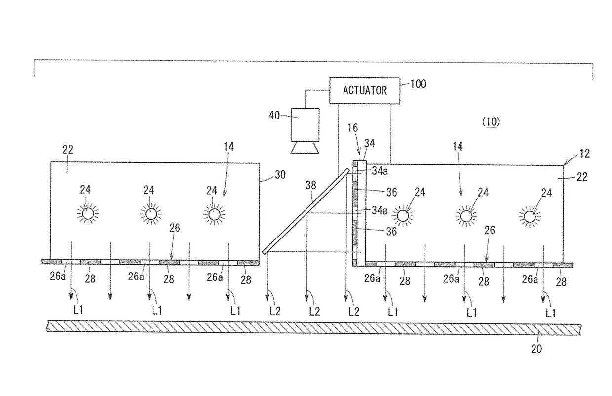
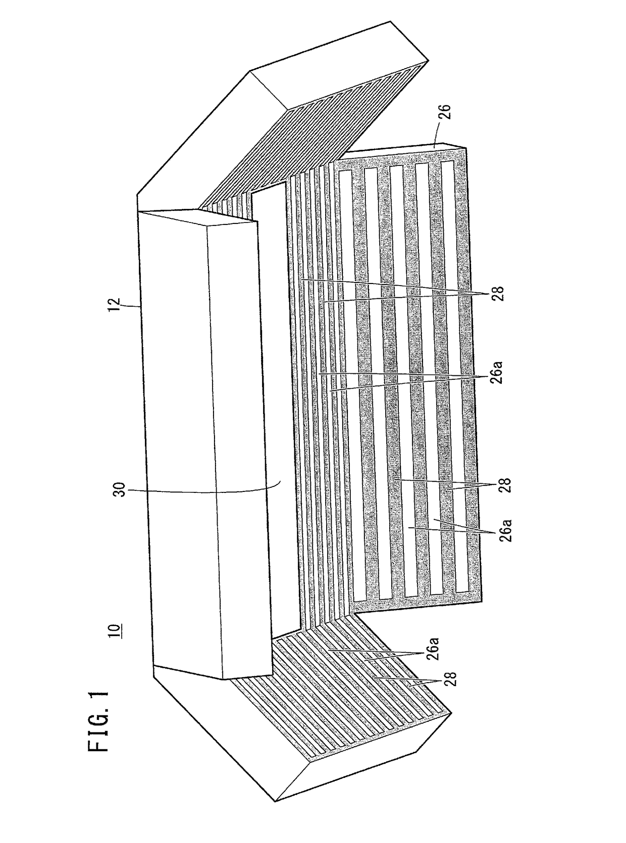
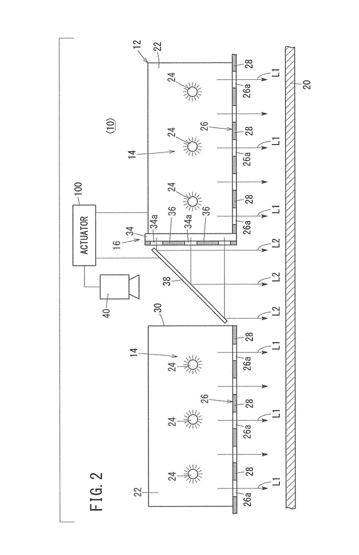
[0037]FIG. 1 is a schematic perspective view showing principal parts of a machine base 12 that constitutes part of a defect inspection apparatus 10 according to an embodiment of the present invention, and FIG. 2 is a schematic vertical cross-sectional view of principal parts of the defect inspection apparatus 10. The defect inspection apparatus 10 includes the machine base 12, a first slit light source 14 (first striped illumination irradiating unit), and a second slit light source 16 (second striped illumination irradiating unit) disposed on the machine base 12. First slit light L1 (first striped illumination) from the first slit light source 14 and second slit light L2 (second striped illumination) from the second slit light source 16 a...


PUM

PropertyMeasurementUnit
defect inspectionaaaaaaaaaa
shapeaaaaaaaaaa
transparentaaaaaaaaaa

Abstract

A defect inspection apparatus includes a first slit light source together with a machine base in which a through hole is formed. A second slit light source and a half mirror are provided inside the through hole. First slit light from the first slit light source is directly incident on an object to be photographed (for example, an automobile body). On the other hand, second slit light from the second slit light source proceeds in a direction perpendicular to the direction in which the first slit light proceeds, and thereafter, is refracted by the half mirror, led out from the through hole, and made incident on the object to be photographed.

Description

CROSS-REFERENCE TO RELATED APPLICATION[0001]This application is based upon and claims the benefit of priority from Japanese Patent Application No. 2016-115641 filed on Jun. 9, 2016, the contents of which are incorporated herein by reference.BACKGROUND OF THE INVENTIONField of the Invention[0002]The present invention relates to a defect inspection method and an apparatus therefor, for inspecting whether or not a defect exists on an object to be photographed by irradiating the object to be photographed with striped illumination.Description of the Related Art[0003]In a manufacturing process for manufacturing automobile bodies, painting is performed on the automobile bodies. Consequently, a coating film is provided. In this instance, protuberances on the order of several tens of μm, or stated otherwise, painting defects may be formed in the coating film. If such painting defects are formed and remain as is, the aesthetic appearance of the automobile body is impaired. For this reason, af...

Claims


Application Information

Patent Timeline
Patent Type & Authority Patents(United States)
IPC IPC(8): G01N21/956G01N21/88G01N21/84G06T7/00G01B11/30G01N21/892G01N21/95
CPCG01N21/956G01B11/30G01N21/8806G01N21/8851G01N21/892G06T7/0004G01N21/95G01N2021/8925G01N21/8921G01N2021/8427G01N2021/8829G01N2021/8924G01N21/8422
Inventor MATSUMOTO, JUNICHI
Owner HONDA MOTOR CO LTD
Why Eureka
Try Eureka