Supercharge Your Innovation With Domain-Expert AI Agents!

Rotary valve assembly having rotatable throttle and intake assemblies

a technology of rotary valves and intake assemblies, which is applied in the direction of oscillatory slide valves, mechanical equipment, machines/engines, etc., can solve the problems of inability to efficiently operate in varying flow conditions, low power output, and inability to get the working fluid in and out of the engine fast enough and efficiently enough

Inactive Publication Date: 2018-02-27
MICROSTEAM
View PDF35 Cites 1 Cited by
  • Summary
  • Abstract
  • Description
  • Claims
  • Application Information

AI Technical Summary

Benefits of technology

The patent describes a rotary valve assembly for an engine that includes a valve housing with a cylindrical bore, an inlet, and an outlet. The assembly also includes an intake assembly and a throttle assembly. The intake assembly has an intake body with a cylindrical bore and intake inlet and intake chamber ports. The throttle assembly has a throttle body with throttle inlet and throttle chamber ports. The intake inlet and throttle inlet ports overlap in a longitudinal direction. The assembly allows for independent rotation of the intake and throttle assemblies, and a vacuum to be applied between the intake and throttle assemblies. The engine may also include a chamber housing with a chamber therein, and the rotary valve assembly may be in fluid communication with the chamber. The technical effects of the invention include improved engine performance and efficiency.

Problems solved by technology

However, turbines often suffer from an inability to efficiently operate in varying flow conditions.
Non-turbine engines (e.g., traditional steam engines) have advantages of being very capable of operating efficiently in varying flow conditions but typically operate at very slow speeds resulting in relatively low power outputs.
One of the primary reasons for past failures to cure this deficiency is the inability to get the working fluid in and out of the engine fast enough and efficiently enough to allow this high speed operation.
One major limitation of the speed of the exchange process is the valvetrain.
Applicant has identified a number of additional deficiencies and problems associated with conventional valvetrains and other associated systems and methods.

Method used


Image

  • Rotary valve assembly having rotatable throttle and intake assemblies
  • Rotary valve assembly having rotatable throttle and intake assemblies
  • Rotary valve assembly having rotatable throttle and intake assemblies

Examples


Embodiment Construction

[0048]Exemplary embodiments of the present invention now will be described more fully hereinafter with reference to the accompanying drawings, in which some, but not all embodiments of the invention are shown. Indeed, the invention may be embodied in many different forms and should not be construed as limited to the exemplary embodiments set forth herein; rather, these embodiments are provided so that this disclosure will satisfy applicable legal requirements. Like reference numerals refer to like elements throughout.

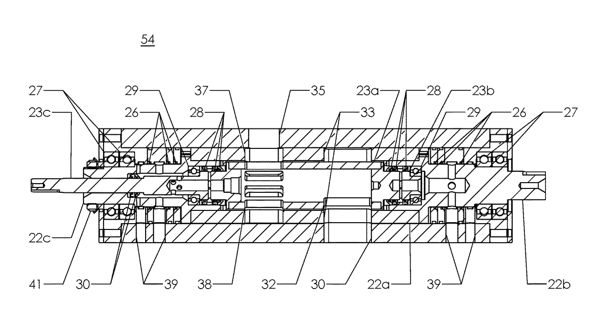
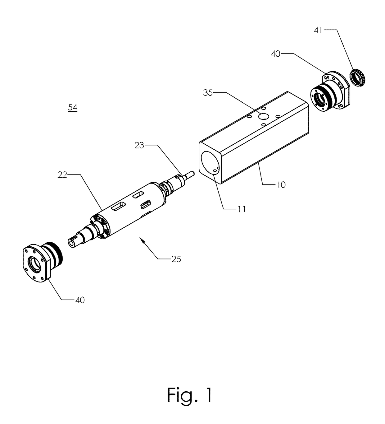
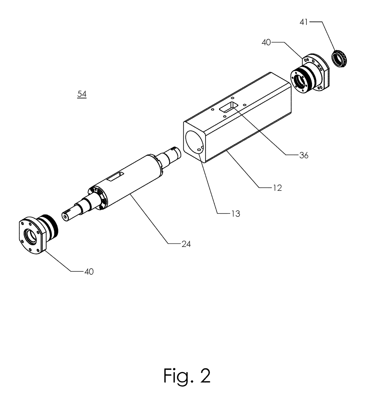
[0049]Some embodiments detailed herein include a rotary valve assembly for use in thermal-fluid and expansion engines, including, for example, steam engines. As detailed herein, embodiments of the rotary valve assembly (e.g., rotary valve assembly 54 shown in FIG. 1-2, 7-9, 12-14, or 18-27) may control the flow of a working fluid (e.g., steam) under pressure into and / or out of an engine chamber to facilitate operation of a drive member (e.g., piston, rotor, etc.). The r...


PUM


Abstract

Provided herein are rotary valve assemblies, engines, and corresponding methods. A rotary valve assembly may include a valve housing defining a cylindrical bore, an inlet, and an outlet. The valve assembly may further include an intake assembly and a throttle assembly arranged concentrically within the cylindrical bore of the valve housing, and the intake assembly and the throttle assembly may rotate independently of one another with respect to a longitudinal axis. During operation of the rotary valve assembly, the valve housing may permit fluid to enter the cylindrical bore of the valve housing via the inlet, the intake assembly may rotate to permit the fluid to flow through the at least one intake inlet port and the at least one throttle inlet port into the throttle body, and the intake assembly may permit the fluid to flow to the outlet from the throttle body.

Description

CROSS-REFERENCE TO RELATED APPLICATIONS[0001]This application is a continuation-in-part of U.S. application Ser. No. 14 / 619,522 filed Feb. 11, 2015, titled “Practical Steam Engine,” which application is incorporated by reference herein in its entirety.BACKGROUND[0002]Many forms of power generation in thermal-fluid systems use engines for converting expansive pressure into mechanical and / or electrical power. Various engines have specific advantages and disadvantages when compared. Turbine engines offer advantages of high speed operation and high power density. However, turbines often suffer from an inability to efficiently operate in varying flow conditions. Non-turbine engines (e.g., traditional steam engines) have advantages of being very capable of operating efficiently in varying flow conditions but typically operate at very slow speeds resulting in relatively low power outputs. A desirable combination is a high speed engine design that would allow the efficient operation at vary...

Claims


Application Information

Patent Timeline
Patent Type & Authority Patents(United States)
IPC IPC(8): F01L7/02F01B17/04F01K7/00F01K13/00
CPCF01L7/023F01B17/04F01L7/027F01K7/00F01K13/006F01B2250/001
Inventor TOLBERT, JOSHUA A.TOLBERT, BENJAMIN J.
Owner MICROSTEAM
Features
  • R&D
  • Intellectual Property
  • Life Sciences
  • Materials
  • Tech Scout
  • Unparalleled Data Quality
  • Higher Quality Content
  • 60% Fewer Hallucinations
Learn More