System and method for controlling forward/reverse rotation of fan

a technology of forward/reverse rotation and control system, which is applied in the direction of rotation direction control, axial flow pump, non-positive displacement fluid engine, etc., to achieve the effect of dissipating heat of electronic devices and minimizing the possibility of erroneous control of switching action

Active Publication Date: 2018-02-27
DELTA ELECTRONICS INC
View PDF2 Cites 7 Cited by
  • Summary
  • Abstract
  • Description
  • Claims
  • Application Information

AI Technical Summary

Benefits of technology

[0009]An object of the present invention provides a control system and a control method for controlling a forward / reverse rotation of a fan. The motor is operated in the forward rotation mode or the reverse rotation mode according to a result of double-checking a duty cycle of a pulse width modulation signal. The control system can dynamically control the forward rotation of the motor to dissipate heat of the electronic device and dynamically control the reverse rotation of the motor to remove dust from the fan blade. Moreover, the control system and the control method can minimize the possibility of erroneously controlling the switching action between the forward rotation and the reverse rotation.
[0010]Another object of the present invention provides a control system and a control method for controlling a forward / reverse rotation of a fan. The control system can control the rotation direction of the motor according to the automatic detecting mechanism and the internal counting mechanism. Consequently, the heat-dissipating demand of the electronic device can be monitored in real time. Moreover, in case that the heat-dissipating demand is lower, the mechanism of automatically eliminating dust can be enabled to enhance the dust-eliminating efficacy.

Problems solved by technology

Consequently, while the motor is in the inertia stop state, the main circuit judges that the fan is normally operated and the protection mechanism is not enabled

Method used


Image

  • System and method for controlling forward/reverse rotation of fan
  • System and method for controlling forward/reverse rotation of fan
  • System and method for controlling forward/reverse rotation of fan

Examples


Embodiment Construction

[0022]The present invention will now be described more specifically with reference to the following embodiments. It is to be noted that the following descriptions of preferred embodiments of this invention are presented herein for purpose of illustration and description only. It is not intended to be exhaustive or to be limited to the precise form disclosed.

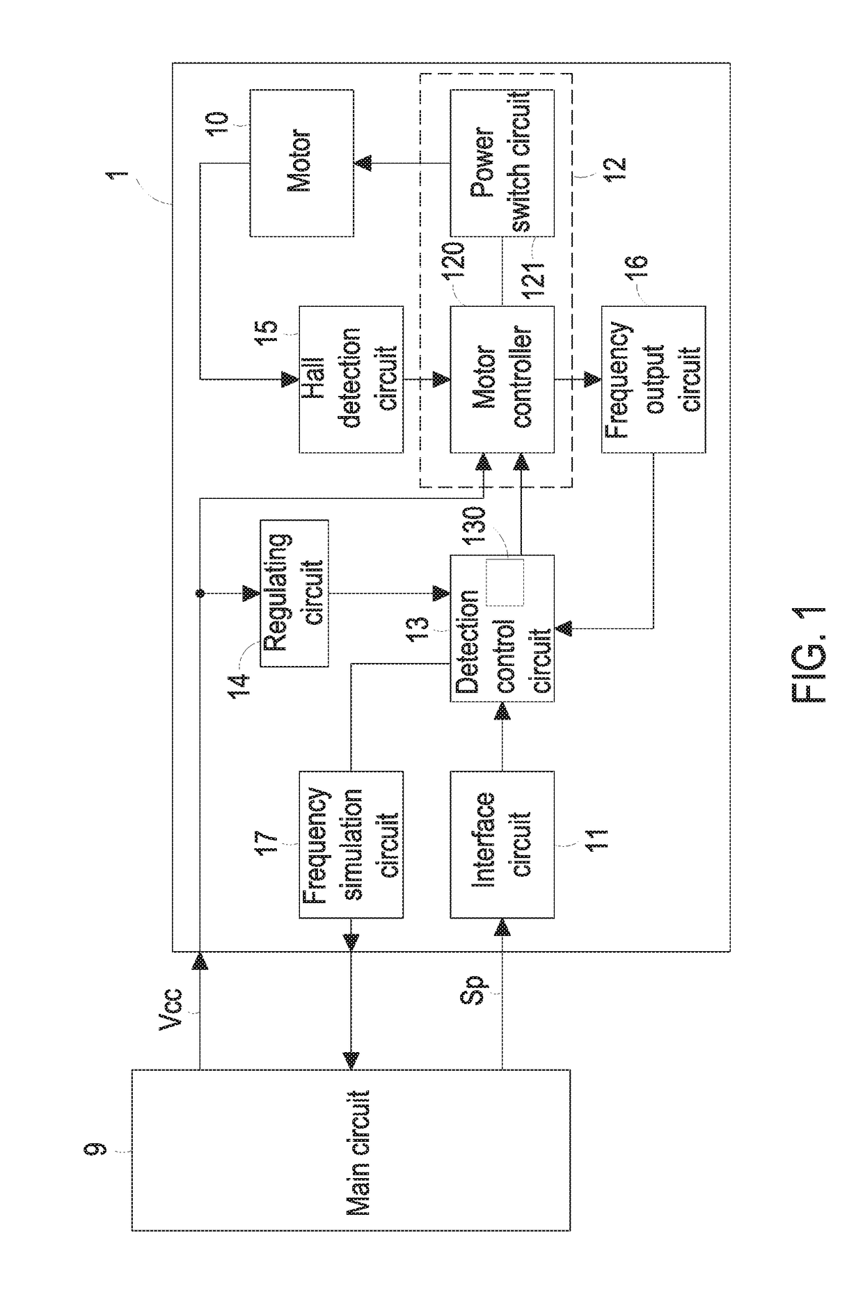
[0023]FIG. 1 is a schematic circuit block diagram illustrating a control system for controlling forward / reverse rotation of a fan according to an embodiment of the present invention. The control system 1 is used for controlling a fan (not shown) of an electronic device. In particular, the control system 1 is used for controlling a forward rotation of the fan to dissipate heat or a reverse rotation of the fan to eliminate dust. The electronic device has a main circuit 9. The main circuit 9 is electrically connected with the control system 1. The main circuit 9 can control the operations of the electronic device. According to the h...


PUM


Abstract

A control system includes a motor, an interface circuit, a motor controller and a detection control circuit. The interface circuit receives and converts a pulse width modulation signal. The fan dissipates heat when the motor is operated in a forward rotation mode and eliminates dust when the motor is operated in a reverse rotation mode. The detection control circuit reads a duty cycle of the converted pulse width modulation signal in real time. When the motor is operated in the forward rotation mode, the detection control circuit drives the motor controller to control the rotation speed of the fan according to the duty cycle. If the duty cycle is lower than or equal to a first threshold value, the detection control circuit drives the motor controller to switch operation mode of the motor from the forward rotation mode to the reverse rotation mode.

Description

CROSS-REFERENCE TO RELATED APPLICATION[0001]This application claims the benefit of U.S. Provisional Application No. 62 / 115,812 filed on Feb. 13, 2015, and entitled “BRUSHLESS FAN CONTROL METHOD AND SYSTEM CAPABLE OF PERFORMING FORWARD AND REVERSE ROTATION TO REMOVE DUST”, the entirety of which is hereby incorporated by reference.FIELD OF THE INVENTION[0002]The present invention relates to a control system and a control method, and more particularly to a control system and a control method for controlling a forward / reverse rotation of a fan.BACKGROUND OF THE INVENTION[0003]Generally, a fan is a very important heat-dissipating mechanism for an electronic device. Since the operating performance, stability and service life of the electronic components of the electronic device are directly influenced by temperature, hence the structure of the fan is designed according to the type and the structure of the electronic device.[0004]The installation of the fan in the electronic device is desi...

Claims


Application Information

Patent Timeline
Patent Type & Authority Patents(United States)
IPC IPC(8): H02P6/30F04D27/00F04D19/00F04D25/08
CPCF04D27/004H02P6/30F04D25/08F04D19/005Y02B30/70
Inventor LIU, CHENG-CHIEHSU, CHIN-PINGSU, TE-SHENGWANG, WEN-CHIH
Owner DELTA ELECTRONICS INC
Why Eureka
Try Eureka