Quick connector

a technology of connectors and connector bodies, applied in the direction of pipe couplings, pipe elements, couplings, etc., can solve the problems of reducing the bending length of the bender, and reducing the bending distan

Active Publication Date: 2018-03-13
SUMITOMO RIKO CO LTD
View PDF14 Cites 7 Cited by
  • Summary
  • Abstract
  • Description
  • Claims
  • Application Information

AI Technical Summary

Benefits of technology

[0011]The retainer includes a base, paired locking legs provided at both ends of the base, allowing passing of the annular boss at the initial position, and locking in the axial direction to the annular boss at the confirmation position, and paired detecting legs provided at both ends of the base and on an inner side in the axial direction from the paired locking legs, bending to the inner side in the axial direction by contact with the annular boss at the initial position, and allowing the retainer to move to the confirmation position in a state where the paired detecting legs bend.
[0014]When the push-in operation of the retainer is carried out in a state where the piped body is not inserted, even if the detecting leg of the retainer is buckled, the bending length is shorter than conventional ones. Thus, the shift amount of the push-in inhibition portion is small. Even with the detecting leg being made smaller, when the piped body is not inserted, the retainer can be inhibited from moving from the initial position to the confirmation position by the push-in operation. That is, the quick connector can make the detecting leg of the retainer smaller, and to securely detect the insertion of the piped body.

Problems solved by technology

In the connector, when the piped body is not inserted in a state where the retainer is placed at the initial position, the push-in operation of the retainer is not enabled.
In particular, since the ends of the detecting legs are locked, the bending of the detecting legs makes the locking of the ends of the detecting legs to the connector body likely to be canceled.
Consequently, the detecting legs of the retainer cannot be easily made smaller.

Method used


Image

  • Quick connector
  • Quick connector
  • Quick connector

Examples


Embodiment Construction

1. Outline of Quick Connector 1

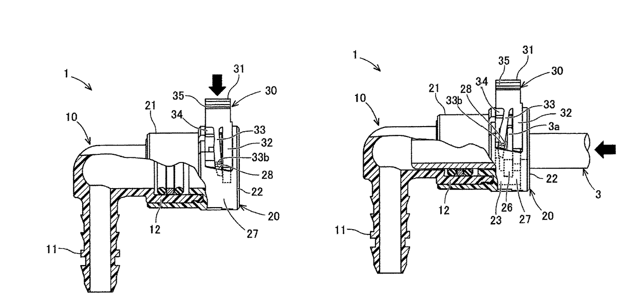
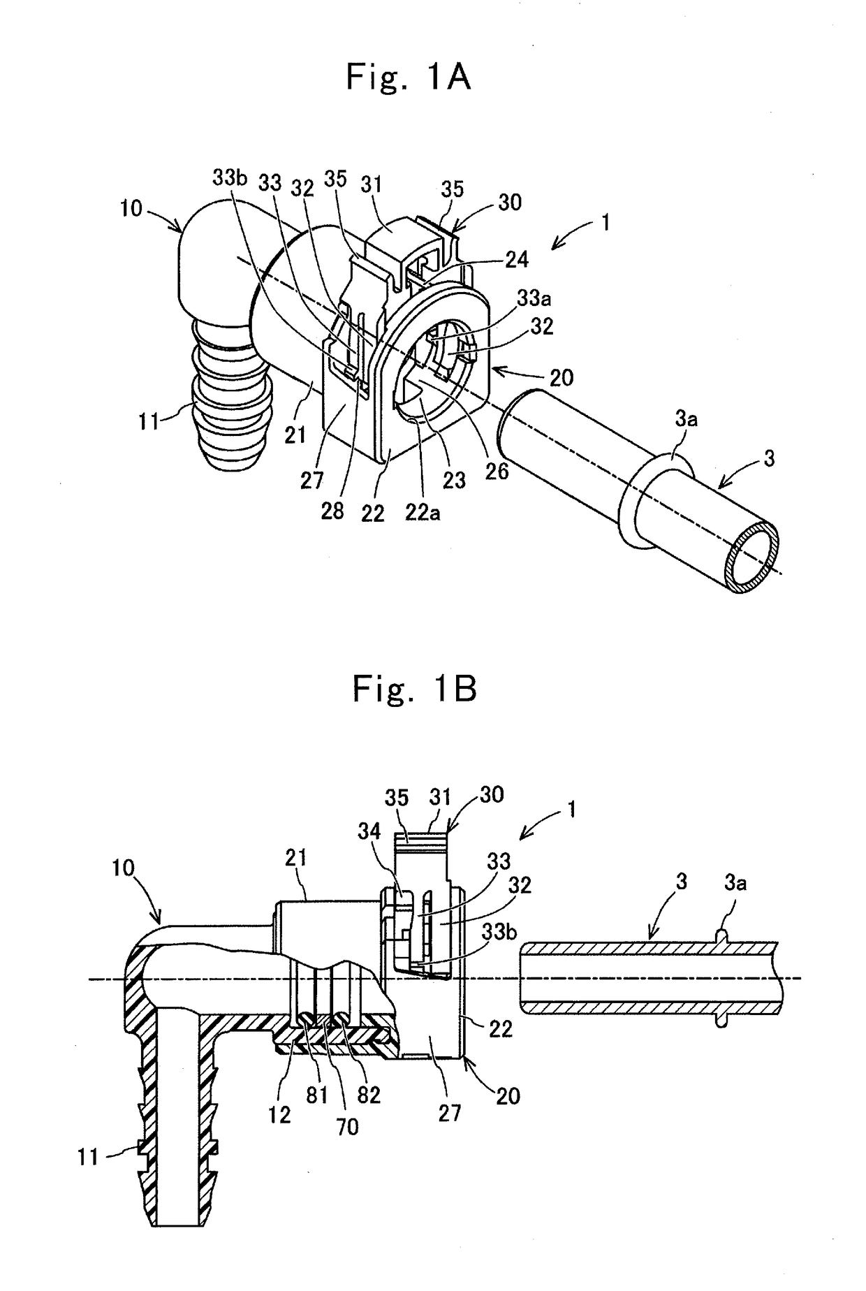
[0042]The outline of a quick connector 1 according to one of the present embodiments will be explained with reference to FIG. 1A, FIG. 1B, and FIG. 2. The quick connector 1 is used for constructing automotive piping, for instance. That is, the quick connector 1 forms a flow passage for distributing fuel, for instance. A resinous tube (not illustrated in the drawings) covers one end side of the quick connector 1, and a piped body 3 is inserted on the other end side of the quick connector 1. In this manner, the resinous tube is coupled together with the piped body 3.

[0043]As illustrated in FIG. 1A and FIG. 1B, the piped body 3 is formed into a tubular shape, and is equipped with an annular boss 3a (flange) which is formed to protrude to the outside in the diametric direction, at a position separated off at a distance from the leading end in the axial direction. In the following description, when viewed from the axial direction of the piped body 3, the pu...


PUM


Abstract

Each detecting leg includes a detection portion provided on the end side of the detecting leg to protrude inward in the diametric direction, and contacting with an annular boss at an initial position, and a push-in inhibition portion provided in the detecting leg on the side of a base from the detection portion, locked in the push-in direction to a connector body in a state where the detecting leg does not bend to the inner side in the axial direction at the initial position, and put in such a state as being not locked in the push-in direction to the connector body in a state where the detecting leg bends to the inner side in the axial direction.

Description

CROSS REFERENCE TO RELATED APPLICATIONS[0001]The present application is a Continuation Application of International Application No. PCT / JP2014 / 076366, filed on Oct. 2, 2014, which claims priority to Japanese Patent Application No. 2013-226767, filed on Oct. 31, 2013, the entire contents of which are incorporated herein by reference in their entireties.BACKGROUND OF THE INVENTION[0002]1. Field of the Invention[0003]The present invention relates to a quick connector to be coupled together with a piped body having an annular boss.[0004]2. Description of the Related Art[0005]Connectors described in JP-A-2008-512607 and JP-A-2006-183833 each have a connector body and a retainer, the retainer being pushed in the connector body, thereby being able to be locked to an annular boss of a piped body. To enable the push-in operation of the retainer, the piped body is required to be inserted at a proper position into the connector body. That is, in the connector, by the push-in operation of the r...

Claims


Application Information

Patent Timeline
Patent Type & Authority Patents(United States)
IPC IPC(8): F16L37/00F16L37/14
CPCF16L37/144F16L2201/10F16L37/0885
Inventor HATANAKA, KAZUKI
Owner SUMITOMO RIKO CO LTD
Why Eureka
Try Eureka