Tool gripper arrangement

a tool and tool technology, applied in the field of tool gripper arrangement, can solve the problems of inability to easily detect inaccurate or wrongly machined parts, insufficient changes to affect the dimensions of the robot arm in a manner, and inability to change in a manner, so as to achieve easy rotation and reduce the influence

Active Publication Date: 2018-03-20
ANCA PTY LTD
View PDF15 Cites 0 Cited by
  • Summary
  • Abstract
  • Description
  • Claims
  • Application Information

AI Technical Summary

Benefits of technology

[0013]Rotational movement of the tool clamp gripper through an arc will generate both horizontal and vertical movement. However, vertical movement can be almost negligible and is in any event not problematic given the inherent compliance in the robot arm in the vertical direction. That means that any vertical movement of the clamped tool that is generated through arcuate movement of the tool clamp gripper during rotation can be accommodated or corrected through compliant movement in the robot arm. The horizontal movement is not corrected by compliant movement in the robot arm given the stiffness of the robot arm in that direction. Thus, the tool which is clamped by the tool clamp gripper can be shifted horizontally to accommodate misalignment of the tool relative to the opening in a collet and the tool can thereafter be inserted into the collet without jamming or misloading.
[0015]Rotation of the tool clamp gripper is free or unrestricted rotation so that the clamp gripper can rotate to the extent necessary for each loading of a tool into a collet. The tool clamp gripper is preferably easily rotated so that there is little or no resistance to rotation and so that rotation can occur quickly and to the extent required for the misalignment to be corrected. Free rotation simply means that the tool clamp gripper is rotatable without being driven or otherwise controlled.
[0021]The offset relationship described above between the axis of the tool clamp gripper and the clamping axis can be such as to space the axes apart any appropriate distance and in any direction subject to the preference that the axes remaining substantially parallel. By that arrangement, relative rotation between the respective axes will create the arcuate movement to provide any horizontal compliance required to load a tool into a collet. In most cases, it is expected that the dimensions of the equipment with which the tool gripping arrangement of the invention is employed will dictate the size of the tool gripping arrangement and thus the allowable offset distance between the respective axes of the tool and the tool clamp gripper. However, as the radius of the rotational arc through which the clamping axis rotates increases, the flatter the movement of a tool in the compliance direction will be. A first prototype of a tool gripping arrangement according to the invention has a radius of about 80 mm and an arc of about 100 micron and in that prototype, the vertical component of the movement was negligible and was easily accommodated through vertical compliance of the robot arm.
[0026]The benefit of a tool gripping arrangement that includes a pair of tool clamp grippers is that as one tool is being loaded into a collet by a first tool clamp gripper, another tool can be clamped by the second tool clamp gripper ready for loading. As the tool of the first tool clamp gripper is loaded into a collet, the second tool clamp gripper can clamp a new tool ready for loading into the collet upon completion of the machining of the tool of the first tool clamp gripper. Once the tool of the first tool clamp gripper has been machined, the first tool clamp gripper can clamp the tool again and remove it from the collet and then the gripping arrangement can be rotated to bring the tool already clamped in the second tool clamp gripper to a position to load into the collet and the first tool clamp gripper can release the machined tool. The first tool clamp gripper can then clamp a further tool for machining once the tool of the second tool clamp gripper has been machined and removed from the collet. This process can be repeated for as many tools there are to be machined.
[0032]The use of a pair of spring biased plungers permits return movement regardless of the direction in which the tool clamp is rotated to load a tool into a collet because clockwise rotation of the tool clamp to load a tool can be returned by one of the spring biased plungers and anti-clockwise movement can be returned by the other of the plungers. Also, the pair of plungers operates together whereby when each plunger is fully extended in the home position of the tool clamp, they apply a light bearing load on the arm which tends to maintain the tool clamp gripper in the home position, so that the tool clamp gripper is correctly positioned to clamp a new tool.
[0033]The spring biased plungers are described above as being set up to apply only a light bearing load on the arm when the tool clamp gripper is in the home position. This is preferred as it minimises the influence that the plungers have resisting rotation of the tool clamp gripper. Thus, the tool clamp gripper is able to easily rotate despite the resistance of the spring biased plungers and to allow the clamped tool to be aligned properly for insertion into the collet. Nevertheless, the biasing influence the plungers exert on the arm can be of any suitable force and in some arrangements of the invention, a load which is greater than a light bearing load can be applied. In one form of the invention, the plungers are depressed and the tool clamp gripper can rotate upon the tool and collet generating a 1 kg load during loading of the tool into the collet opening in a misaligned position. In this form of the invention, the springs of the spring plungers are preloaded to about 35.3 N and the spring rate is about 2 N / mm. The preloading is provided so that the spring biased plungers will hold the weight of the tool clamp gripper at the home position until the preload is exceeded by the load generated between the tool and the collet. These figures depend on various factors including the weight of the tool clamp gripper and the moment generated during rotation of the tool clamp gripper from the point of rotation to the centre of mass of the gripper.

Problems solved by technology

For example, many factories within which relevant grinding or milling machines operate, are not temperature controlled, so the temperature can fluctuate during the day.
Even only small dimensional changes can be sufficient to affect the dimensions of the robot arm in a manner that becomes problematic as explained below.
The change in accuracy will not necessarily affect arrangements where the clearance between the tool and the collet is large, but where there is very low clearance, such as between 0 to 20 microns, the change in accuracy can result in either failed loading such as jamming of the tool within the collet, or incorrect loading, the latter of which can result in inaccurately or wrongly machined parts.
For example, where an inaccuracy occurs in loading a tool into a collet so that the longitudinal centre line of a tool becomes misaligned with the centre line of the collet, the tool can engage against one side of the collet and can tend to bend.
Because the misalignment can be so small, it will not be easily detectable, and often only becomes apparent once the tool has been machined.
If the inaccuracy is not discovered for some time, many tools can be inaccurately machined resulting in significant wasted time and materials.
Accordingly, it is the case that calibration of the arm needs to occur from time to time, particularly where significant temperature and / or humidity changes occur throughout the day, and that means down time for the machinery and increased personnel interaction with the machinery.
In addition, there is no ability to check when recalibration is required.
Thus, recalibration occurs as the machine operator decides or according to a predetermined schedule, or when it is clearly apparent that tools are not being loaded correctly or are being machined inaccurately.
Such arms which operate horizontally tend to have a small movement or “compliance” in the vertical direction, but are very stiff in the horizontal direction and therefore lack movement or compliance in that direction.
In such arms as discussed above, it follows that it is lack of compliance in the horizontal direction that results in misloading of a tool in the collet and subsequent inaccurate machining, or a complete failure to load because the tool is positioned to load offset from the opening of the collet.

Method used


Image

  • Tool gripper arrangement
  • Tool gripper arrangement
  • Tool gripper arrangement

Examples


Embodiment Construction

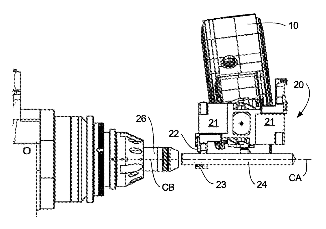
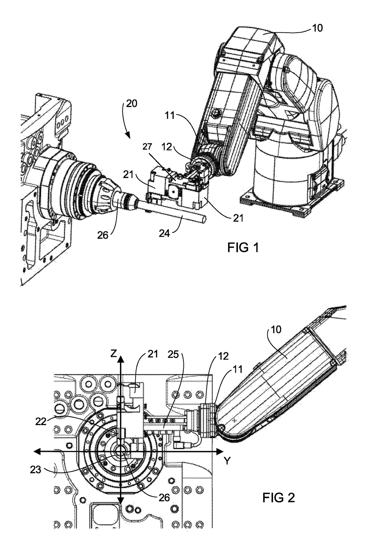
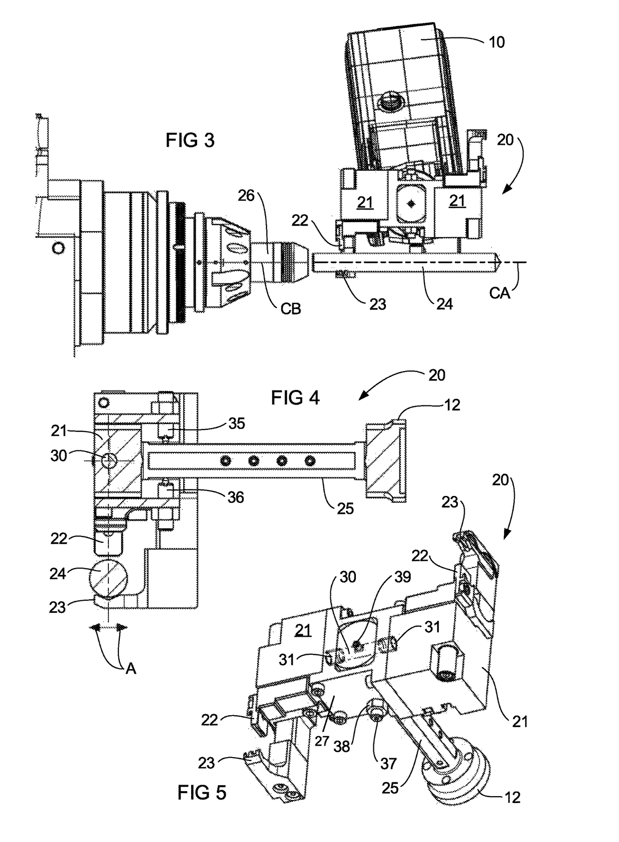
[0041]FIGS. 1 to 3 illustrate the invention in a position for loading a tool into a collet of a grinding or milling machine. FIG. 1 thus shows a robot arm 10 which has an end effector 11 and in turn, to which is attached the base 12 of a tool gripping arrangement or robot gripper head 20. The tool gripping arrangement 20 includes a pair of tool clamp grippers 21 that each includes a pair of gripper fingers 22 and 23 (see FIG. 4) for gripping a tool 24 and the tool gripping arrangement 20 is attached to the end effector 11 via a shaft or arm 25.

[0042]The tool clamp grippers 21 are of a standard form and their operation would be known to persons skilled in the art. Accordingly, the manner in which the tool clamp grippers 21 operate to clamp a tool is not further discussed herein. The tool grippers are mounted to a body 27 for rotation relative to the body 27. The arm 25 extends into the body 27 and is fixed to the body.

[0043]One of the tool clamp grippers 21 is shown gripping the tool...


PUM


Abstract

A tool gripping arrangement for loading an elongate tool having a lengthwise axis into a collet. The tool gripping arrangement includes a tool clamp comprising a pair of tool clamp grippers for clamping the tool along a clamping axis. The tool gripping arrangement further includes a mounting arrangement for mounting the gripping arrangement to a robot arm, the tool clamp being mounted for free rotation relative to the mounting arrangement.

Description

TECHNICAL FIELD[0001]The present invention provides a tool gripping arrangement which is hereinafter referred to as a “robot gripper head” and which has principally been developed for loading a tool or tool blank into the collet of a grinding or milling machine. The invention has been developed principally for loading tools into collets where extremely low clearances exist.BACKGROUND OF INVENTION[0002]The following discussion of the background to the invention is intended to facilitate an understanding of the invention. However, it should be appreciated that the discussion is not an acknowledgement or admission that any of the material referred to was published, known or part of the common general knowledge as at the priority date of the application.[0003]The loading of tools or tool blanks (hereinafter “tools”) into the collet of a grinding or milling machine is usually either a manual operation, or a robot controlled operation. More sophisticated grinding or milling machines emplo...

Claims


Application Information

Patent Timeline
Patent Type & Authority Patents(United States)
IPC IPC(8): B23Q3/155B25J17/02
CPCB23Q3/1554B25J17/0208Y10S901/31Y10S483/902B23Q2003/155428B23Q2003/155418B23Q2003/155411B23Q3/1552B23Q3/157B24B45/003B23Q2003/155404B23Q2003/155421B23Q2003/155432B23Q3/15713
Inventor GARNHAM, JOHN DAVIDMCGRATH, BENN
Owner ANCA PTY LTD
Why Eureka
Try Eureka