
System for redundant power supply to a data center

a data center and power supply technology, applied in the field of data center circuitry, can solve the problems of data center electric power consumption, high cost of double equipment, and the use of redundant equipment in emergency cases,

Active Publication Date: 2018-03-20
BIGZ TECH INC
View PDF20 Cites 3 Cited by
  • Summary
  • Abstract
  • Description
  • Claims
  • Application Information

AI Technical Summary

Benefits of technology

[0031]As will be realized, the subject matter disclosed and claimed is capable of modifications in various respects, all without departing from the scope of the claims. Accordingly, the drawings and the description are to be regarded as illustrative in nature, and not as restrictive and the full scope of the subject matter is set forth in the claims.

Problems solved by technology

Data centers consume considerably large amounts of electric power.
However, doubling the equipment is costly.
This disadvantage is emphasized by the fact that redundant equipment is usually used in emergency cases only, i.e., it remains almost unused.
In this industrial environment, allocating capital to power-generating equipment that occupies space, requires maintenance and otherwise has a very low capacity factor is undesirable.

Method used


Image

  • System for redundant power supply to a data center
  • System for redundant power supply to a data center
  • System for redundant power supply to a data center

Examples


Embodiment Construction

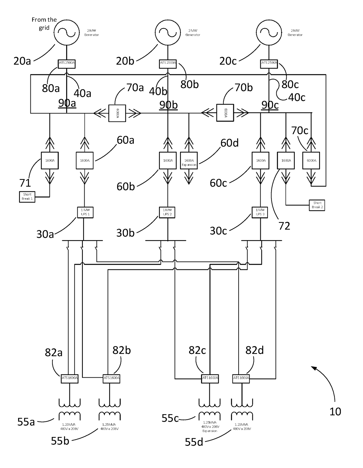
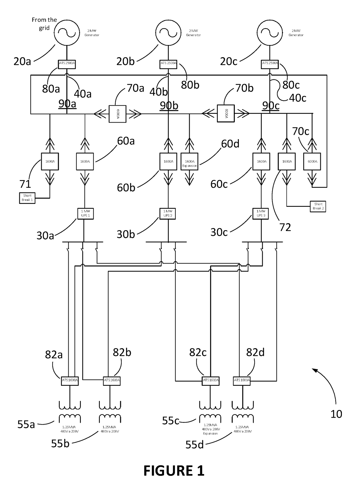
[0038]There is described a system 10, shown in FIG. 1, providing redundant electric supply to a load such as a data center. The configuration described below allows for N+1 redundancy at the generator and UPS levels to feed the electrical distribution with 2N redundancy.

[0039]The system 10 comprises a bank of power sources 20a, 20b, 20c, aka generators, generating electric power for the circuit, a bank of UPS units 30a, 30b, 30c and electrical panels 50a, 50b receiving the electric power.

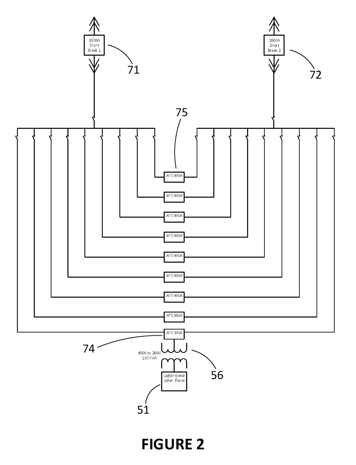
[0040]At the electrical distribution side, the system 10 usually comprises 2N transformers 55a, 55b, 55c, 55d directly connected to N electrical panels 50a, 50b (see FIG. 4). The N electrical panels 50a, 50b are fed in a redundant manner by N+1 UPS units 30a, 30b, 30c. The electric power is provided to the N+1 UPS units 30a, 30b, 30c by N+1 power sources 20a, 20b, 20c.

[0041]Therefore, the system described herein displays N+1 redundancy at the generator and UPS levels to feed the electrical distribu...


PUM


Abstract

There is described a circuit to supply electric power to N electrical panels. The circuit comprises N+1 blockbars, each one of the blockbars being for connection to an automatic transfer switch (ATS) of a power source, each one of the blockbars being connected to at least two other ones of the N+1 blockbars via a segregating switchgear. The circuit further comprises N+1 UPS units, each one of the UPS units being for connection to a dedicated one of the blockbars via a dedicated switchgear. The circuit further comprises 2N power outputs, each one of the N electrical panels being connected to 2 of the 2N power outputs, each one of the 2N power outputs being connected to 2 of the N+1 UPS units. This configuration allows for N+1 redundancy at the generator and UPS levels to feed the electrical distribution with 2N redundancy.

Description

BACKGROUND[0001](a) Field[0002]The subject matter disclosed generally relates to circuitry for electric supply to data centers. More specifically, it relates to circuit architecture providing redundant electric supply to data centers.[0003](b) Related Prior Art[0004]Data centers consume considerably large amounts of electric power. The servers making up a data center need to be constantly supplied in electric power, i.e., in an uninterrupted manner. To a lesser extent, the same holds for other components such as fans and air conditioning which contribute to the functioning of the data center.[0005]Redundancy is usually provided by doubling the equipment to ensure the uninterrupted operation of the data center. However, doubling the equipment is costly. This disadvantage is emphasized by the fact that redundant equipment is usually used in emergency cases only, i.e., it remains almost unused. In this industrial environment, allocating capital to power-generating equipment that occupi...

Claims


Application Information

Patent Timeline
Patent Type & Authority Patents(United States)
IPC IPC(8): H02J9/06
CPCH02J9/06H02J9/062H02J3/38
Inventor AHDOOT, ELIOT
Owner BIGZ TECH INC
Learn More