

Shatter-resistant, optically-transparent panels and methods of use of the panels for on-site retrofitting and reinforcing of passageways
a technology of optical transparency and glass, applied in the direction of parallel plane units, other domestic articles, synthetic resin layered products, etc., can solve the problems of high cost of complex windows, excessive weight of common doorways of public buildings, and inconvenient use of complex windows, etc., to achieve efficient and rapid enhancement of the security of public schools, efficient and inexpensive
- Summary
- Abstract
- Description
- Claims
- Application Information
AI Technical Summary
Benefits of technology
Problems solved by technology
Method used
Image

Examples
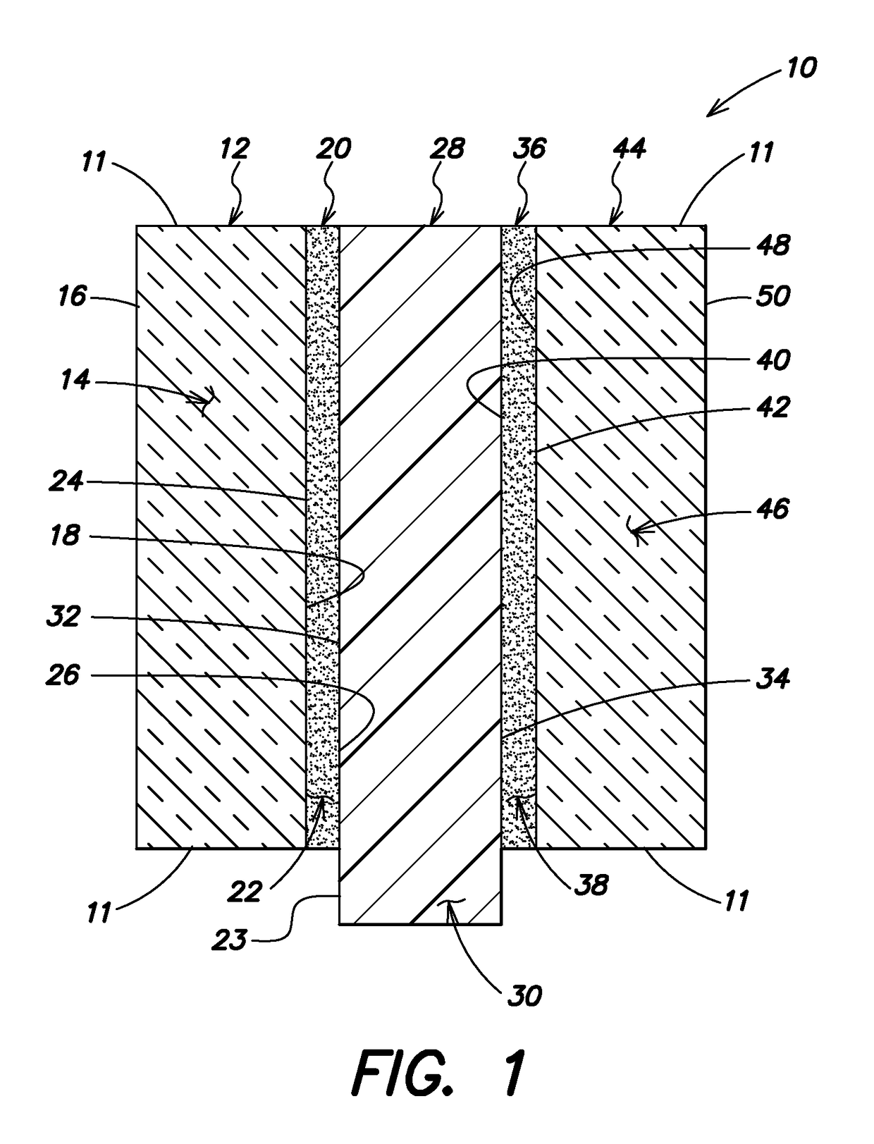
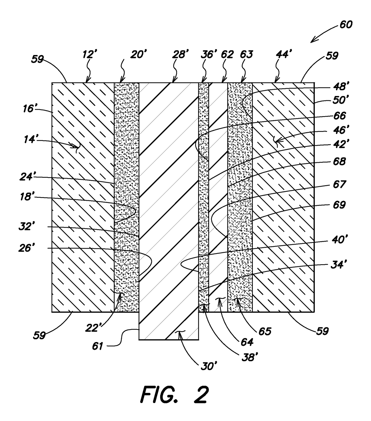
embodiment 60
[0059]After reinforcing the stops 90, 94, the exterior stops 94 are removed, and then an interior bead 104A of about 3.048 mm [0.120 (⅛) inch] diameter of the blast proof caulking 104A is applied at a base of the interior stop 90 and the top surface 98 of the door frame compression receiver 92 so that the bead 104A surrounds an entire perimeter of the passageway frame 72. Then, the method includes installing one of the thin panel embodiment 10 and the thick panel embodiment 60 of the shatter-resistant, optically-transparent panel 10, 60 into the passageway frame 72 adjacent the bead 104A of caulking.
[0060]Next, another or exterior 3.048 mm [0.120 (⅛) inch] bead 104B of the blast proof caulking is applied along an entire exterior perimeter of the selected panel 10, 60 where the panel 10, 60 meets the top surface 98 of the door frame compression receiver 92. The exterior stops 94 are then installed into the frame 72 so that holes drilled in the stops 94 align with holes drilled in the...
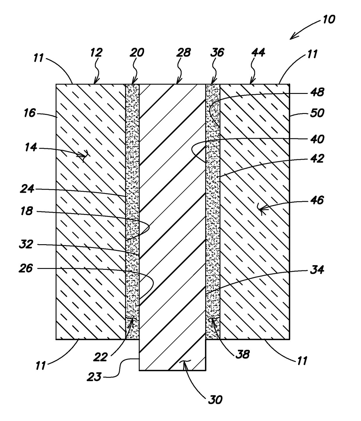
embodiment 10
[0065]The optically-transparent panel 204 is secured within the bead of blast proof caulking 232 upon the setting block 240, and is also secured adjacent the first layer of glazing tape 236. The optically-transparent panel may be either the above described thin embodiment of the transparent panel 10 (shown in FIG. 1) or the thick embodiment of the transparent panel 60 (shown in FIG. 2). For purpose of efficiency, the aforesaid thin 10 and thick 60 embodiments of the transparent panel are also described as a shatter-resistant five-layer thin panel 10, 204 and a shatter-resistant seven-layer thick panel 60, wherein each of the panels includes opposed first and second glass sheets 14, 46, 14″, 46″ (layers of the thin embodiment 10 shown in FIGS. 6 and 7 for the five-layer thin panel 204 are shown as double primes of the reference numerals shown in FIG. 1), first and second urethane sheets 22, 38, 22″, 38″ between the first and second glass sheets, and a polycarbonate sheet 30, 30″ betw...
first embodiment
[0066]the reinforced passageway 200 also includes a second stop 242 having an outside wall 244 of the second stop 242 that is secured to the top structural surface 210 and is also secured adjacent the top edge 214 of the second structural surface 208. The outside wall 244 of the second stop 242 extends in parallel association with and away from the second structural surface 208. The second stop 242 also includes an inside wall 246 of the second stop 242 that is also secured to the top structural surface 210 and is opposed to the outside wall 244. The inside wall 246 extends in parallel association with the outside wall 244 away from the top structural surface 210. FIG. 5 shows that the integral first stop and base plate 218 along with the second stop 242 are applied to descend upon the top structural surface 210 from above the surface 210, as represented in FIG. 5 by directional arrows 247. FIGS. 6 and 7 show the integral first stop and base plate 218 along with the second stop 242 ...
PUM
| Property | Measurement | Unit |
|---|---|---|
| thickness | aaaaa | aaaaa |
| thickness | aaaaa | aaaaa |
| thickness | aaaaa | aaaaa |
Abstract
Description
Claims
Application Information