Coolant bridging line for a gas turbine, which coolant bridging line can be inserted into a hollow, cooled turbine blade

a technology of cooling line and gas turbine, which is applied in the direction of machines/engines, stators, mechanical equipment, etc., can solve the problems of high heat generation, high cost, and inability to use cooling line to improve service li

Inactive Publication Date: 2018-03-27
SIEMENS AG
View PDF30 Cites 2 Cited by
  • Summary
  • Abstract
  • Description
  • Claims
  • Application Information

AI Technical Summary

Benefits of technology

[0007]Embodiments of the invention are hence based on an object of indicating a coolant bridging line which permits a further increase in the service life of the components of the gas turbine, and at the same time the highest possible efficiency.
[0012]Advantageously, the means comprise to that end a coating which, also advantageously, comprises a ceramic material. Less thermal energy is thus introduced into the coolant bridging line since the interaction between the coolant transported within and the surroundings is reduced. This improves the cooling effect of the coolant at the point of action, since the efficiency of the coolant transport is increased.
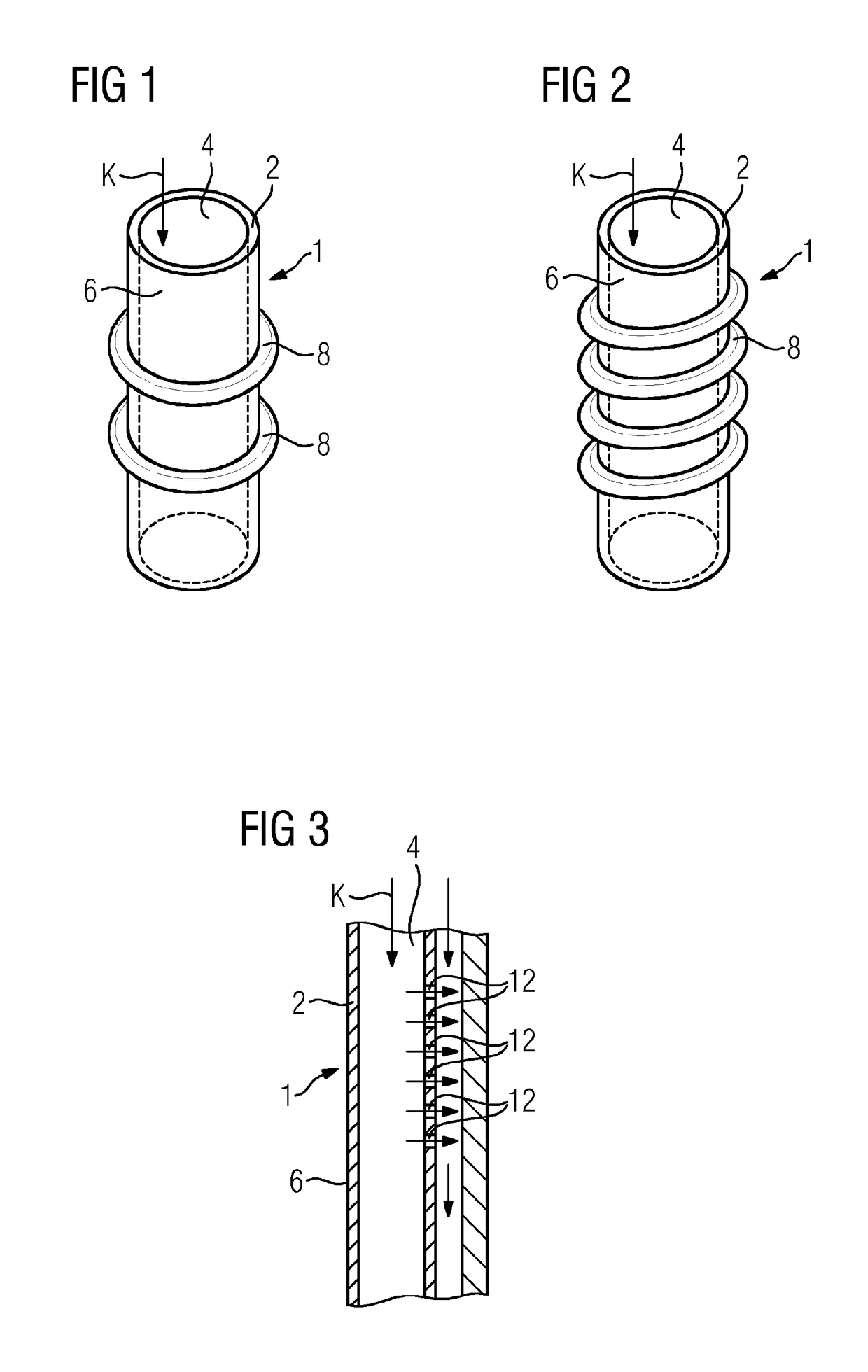
[0013]In an alternative or additional configuration, the means comprise turbulators. This is particularly advantageous if some components to be cooled cause excessive consumption of coolant. Such excessive consumption namely reduces the efficiency of the entire gas turbine. With the aid of turbulators, which are arranged on the inside of the wall of the coolant bridging line, eddies are generated such that the pipe resistance in the line increases and thus the pressure loss is increased. Alternatively or in addition, turbulators may also be affixed to the outer side of the coolant bridging line. This also raises a possibility of increasing the flexibility of configuration. Since turbulators of this type on the outer side increase the introduction of heat into the coolant flowing inside the bridging line, this variant may advantageously be combined with the coating.
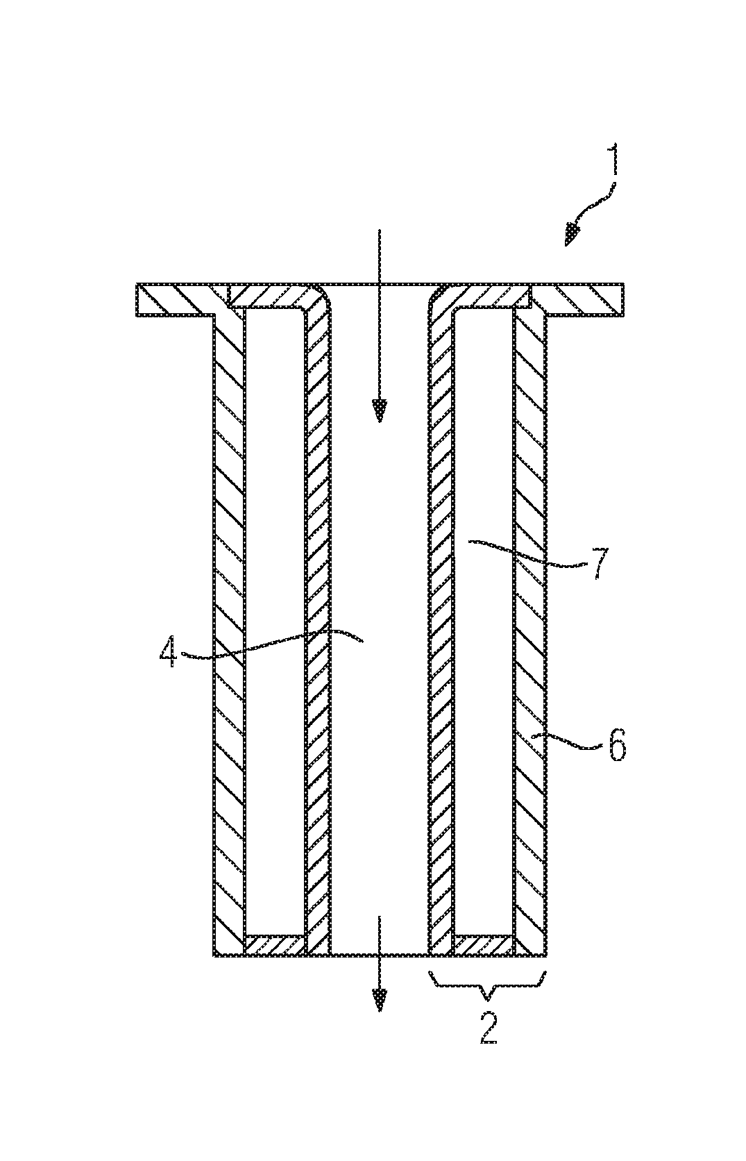
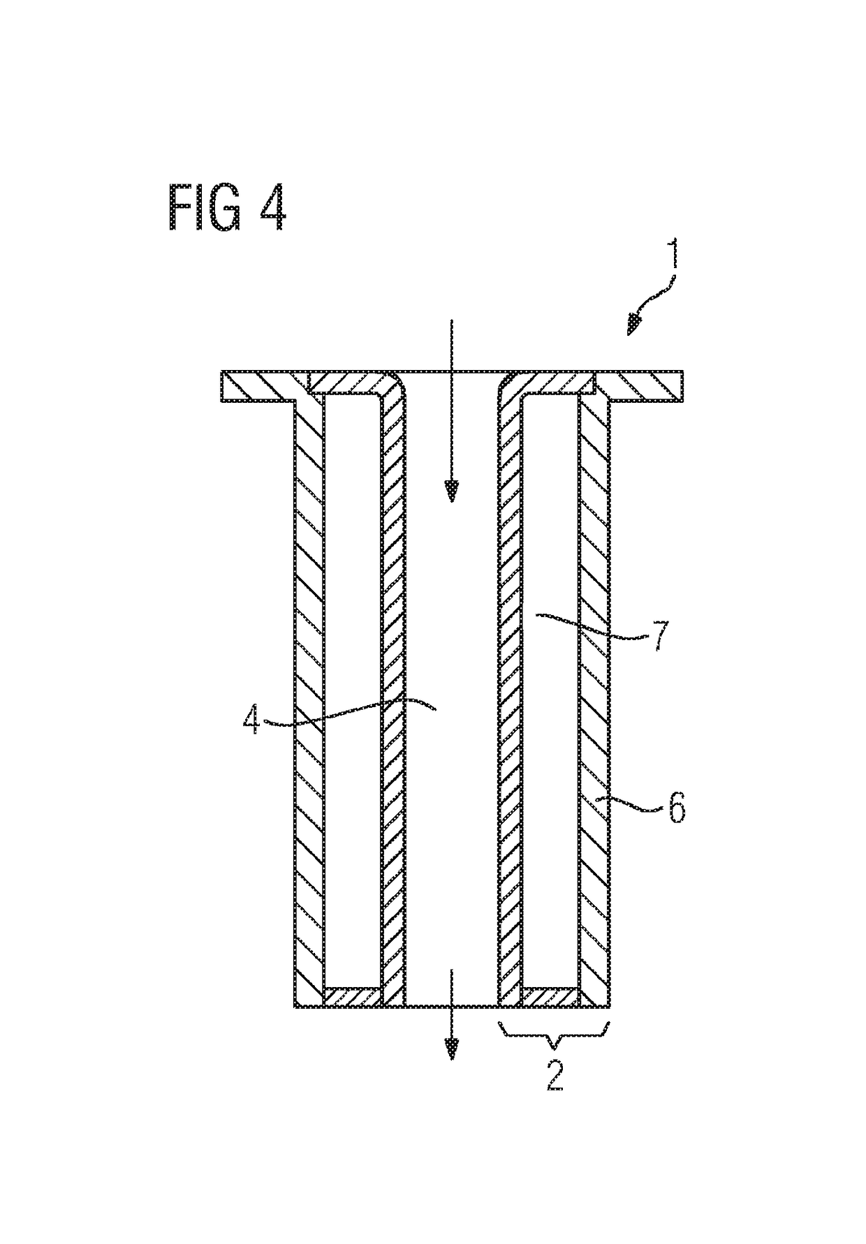
[0014]In a further advantageous configuration, the means comprise a number of openings in the wall of the coolant bridging line. A configuration of this type offers particular advantages if, during operation, components in the region of the coolant line experience a high thermal load. Specifically if an excessive thermal load is detected only when the gas turbine is in operation, i.e. after the construction phase, comprehensive constructive changes are frequently associated with high costs and technical complexity. In this case, by introducing openings into the coolant bridging line, it is possible to provide relief quickly and cost-effectively, since in affected areas coolant from the bridging line reaches the affected component directly as an impingement coolant. According to a further advantageous configuration, as the means for changing the heat transfer, the wall is of hollow design. By virtue of this configuration, which is to be referred to as a double-walled construction, thermal conduction from the outer side to the inner side is further reduced, by means of which, when the coolant bridging line is used as intended in a relatively hot environment, the introduction of heat into the coolant flowing along the inner side is kept comparatively low. Preferably, in that context, the cavity of the wall is hermetically sealed with respect to the inner side and the outer side, such that an exchange or even mixing of hotter, outer medium with the cavity medium is prevented. The sealing thus results in reduced thermal conductivity of the cavity medium. More preferably, the pressure within the cavity is negative with respect to an average atmospheric pressure. The lower the cavity pressure, the more medium was removed from the cavity before the latter was sealed and the lower its thermal conductivity, which has the effect of keeping the temperature of the coolant flowing along the inner side more constant.
[0017]The advantages associated with embodiments of the invention include in particular in the fact that, by virtue of the modification to the coolant bridging lines with respect to their thermal and fluidic properties, a flexible adaptation to temperature distributions within a gas turbine, which arise during operation, becomes possible. By virtue of such modifications, quick solutions to problems, for example in the event of excessive temperatures at individual components, are possible. The coolant bridging line thus serves the dual purpose of transporting coolant and cooling or controlling pressure losses in the cooling system.

Problems solved by technology

In this context, it has surprisingly been found that the coolant bridging lines used have hitherto in no way been used to improve service life while maintaining a constant efficiency.
However, it is specifically between the guide blade root and the guide blade head that the thermal load on the coolant which is to be conveyed through—but as far as possible not heated—is particularly high.

Method used


Image

  • Coolant bridging line for a gas turbine, which coolant bridging line can be inserted into a hollow, cooled turbine blade
  • Coolant bridging line for a gas turbine, which coolant bridging line can be inserted into a hollow, cooled turbine blade
  • Coolant bridging line for a gas turbine, which coolant bridging line can be inserted into a hollow, cooled turbine blade

Examples


Embodiment Construction

[0024]Identical parts are provided with the same reference signs in all figures.

[0025]FIG. 1 shows a cylindrical coolant bridging line 1. This is inserted into a hollow, cooled turbine guide blade (not shown) and extends between the blade roots of the turbine guide blade. The coolant bridging line 1 has a wall 2 which separates the inner side 4 and the outer side 6 of the coolant bridging line 1. Coolant K, in the exemplary embodiment air, is conveyed inside the coolant bridging line 1.

[0026]Annular turbulators 8 are arranged on the outer side 6. In the alternative exemplary embodiment according to FIG. 2, however, the turbulators 8 are arranged in a helical manner. Equally, turbulators not shown in more detail can be arranged on the inner side of the coolant bridging line 1. In addition, the coolant bridging lines according to FIGS. 1 and 2 are provided with a ceramic coating.

[0027]FIG. 3 shows a coolant bridging line 1 together with the adjacent end side 10 of the guide blade into...


PUM

PropertyMeasurementUnit
angleaaaaaaaaaa
mechanically useful poweraaaaaaaaaa
thermal stressesaaaaaaaaaa

Abstract

A coolant bridging line for a gas turbine having inner and outer sides which are separated by a wall, wherein the coolant bridging line extends from a first component of the gas turbine to a second component of the gas turbine is provided herein. The coolant bridging line for a gas turbine provides a further increase in the service life of the components of the gas turbine possible with a degree of efficiency which is nevertheless as high as possible. To this end, the coolant bridging line has means which change the heat transfer between and / or the flow conditions on the inner and outer sides.

Description

CROSS REFERENCE TO RELATED APPLICATIONS[0001]This application is the US National Stage of International Application No. PCT / EP2013 / 059859 filed May 14, 2013, and claims the benefit thereof. The International Application claims the benefit of German Application No. DE 102012209549.7 filed Jun. 6, 2012. All of the applications are incorporated by reference herein in their entirety.FIELD OF INVENTION[0002]The invention relates to a coolant bridging line for a gas turbine, which coolant bridging line can be inserted into a hollow, cooled turbine blade and has inner and outer sides separated by a wall, wherein the coolant bridging line extends from a first component of the gas turbine to a second component of the gas turbine.BACKGROUND OF INVENTION[0003]A gas turbine is a turbomachine in which a gas under pressure expands. It includes a turbine or expander, a compressor connected upstream thereof, and a combustor connected between the two. All of the blades of the compressor and of the t...

Claims


Application Information

Patent Timeline
Patent Type & Authority Patents(United States)
IPC IPC(8): F01D9/02F01D5/14F01D9/06F01D5/18
CPCF01D5/147F01D5/187F01D9/02F01D9/065Y02T50/675F05D2260/201F05D2260/2212F05D2260/231F05D2300/20F01D5/189Y02T50/60F01D5/18
Inventor AHMAD, FATHI
Owner SIEMENS AG
Why Eureka
Try Eureka