Cryogenic fuel system and method for delivering fuel in an aircraft

a fuel system and cryogenic technology, applied in the field of cryogenic fuel system and delivery method of fuel in aircraft, can solve the problem of low engine efficiency

Active Publication Date: 2018-04-03
GENERAL ELECTRIC CO
View PDF15 Cites 9 Cited by
  • Summary
  • Abstract
  • Description
  • Claims
  • Application Information

AI Technical Summary

Problems solved by technology

Use of compressor air for cooling may lower efficiency of the engine system.

Method used


Image

  • Cryogenic fuel system and method for delivering fuel in an aircraft
  • Cryogenic fuel system and method for delivering fuel in an aircraft
  • Cryogenic fuel system and method for delivering fuel in an aircraft

Examples


Embodiment Construction

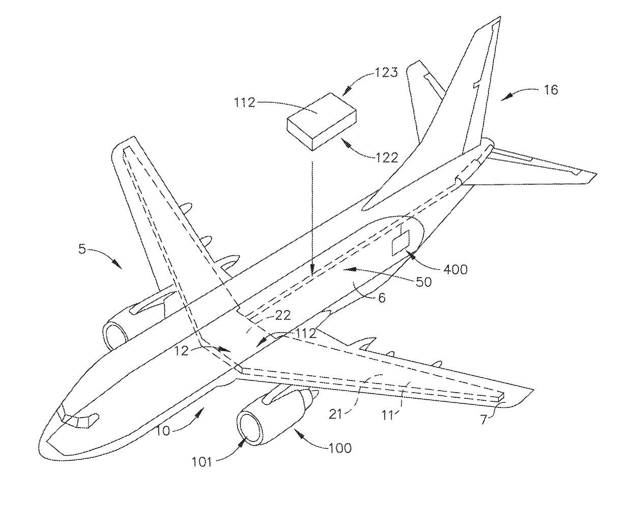
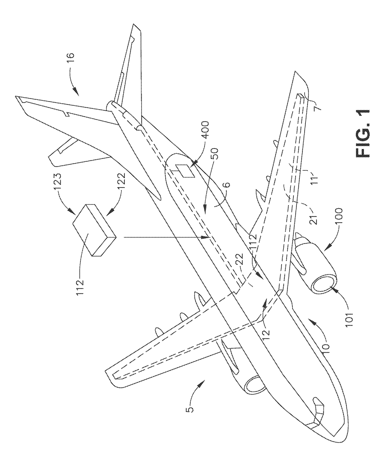
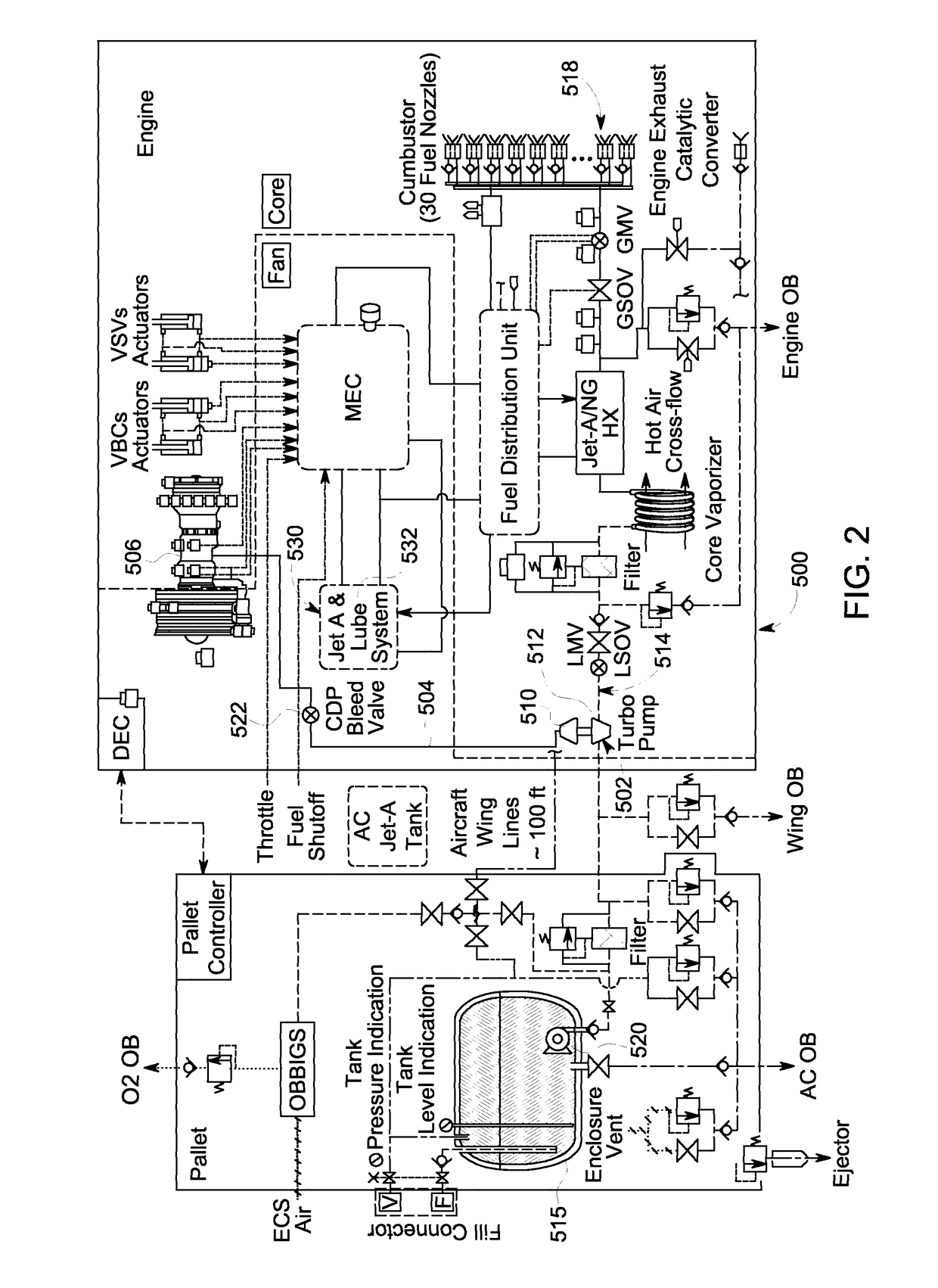
[0005]In one aspect, an embodiment of the invention relates to a cryogenic fuel system for an aircraft having a turbine engine with a compressor section and a combustion chamber, including a tank for storing cryogenic fuel, a supply line operably coupling the tank to the combustion chamber and a pump coupling the tank to the supply line to pump the cryogenic fuel at high pressure through the supply line where the pump is operably coupled to the compressor such that operation of the turbine engine drives the pump.

[0006]In another aspect, an embodiment of the invention relates to a method for delivering fuel in a fuel system to a turbine engine having a combustion section and a compressor section, including pressurizing the fuel provided to the combustion section of the turbine engine utilizing a turbopump driven by compressor discharge pressure from the turbine engine.

BRIEF DESCRIPTION OF THE DRAWINGS

[0007]The technology described herein may be best understood by reference to the fol...


PUM


Abstract

A cryogenic fuel system for an aircraft having a turbine engine with a compressor section and a combustion chamber, including a tank for storing cryogenic fuel, a supply line operably coupling the tank to the combustion chamber and a pump coupling the tank to the supply line to pump the cryogenic fuel at high pressure through the supply line where the pump is operably coupled to the compressor such that operation of the turbine engine drives the pump and a method for delivering fuel in a fuel system to a turbine engine.

Description

CROSS-REFERENCE TO RELATED APPLICATIONS[0001]This application claims the benefit of U.S. Provisional Patent Application No. 61 / 747,169, filed on Dec. 28, 2012, which is incorporated herein in its entirety.BACKGROUND OF THE INVENTION[0002]The technology described herein relates generally to aircraft systems, and more specifically to aircraft systems using dual fuels in an aviation gas turbine engine and a method of operating same.[0003]Certain cryogenic fuels such as liquefied natural gas (LNG) may be cheaper than conventional jet fuels. Current approaches to cooling in conventional gas turbine applications use compressed air or conventional liquid fuel. Use of compressor air for cooling may lower efficiency of the engine system.[0004]Accordingly, it would be desirable to have aircraft systems using dual fuels in an aviation gas turbine engine. It would be desirable to have aircraft systems that can be propelled by aviation gas turbine engines that can be operated using conventional ...

Claims


Application Information

Patent Timeline
Patent Type & Authority Patents(United States)
IPC IPC(8): B64D37/30F02C7/236F02C3/22F02C7/224F02C6/08F02C9/40
CPCB64D37/30F02C3/22F02C6/08F02C7/236F02C9/40F02C7/224Y02T50/672Y02T50/60
Inventor KAMATH, DEEPAK MANOHARBUCHHOLZ, TODD JAMESBALADI, MEHDI MILANIEPSTEIN, MICHAEL JAY
Owner GENERAL ELECTRIC CO
Why Eureka
Try Eureka