Method for making pouches and a pouch as such

a technology of pouches and pouches, applied in the field of making pouches and pouches, can solve the problem of only restricting the penetration of water through the web material

Active Publication Date: 2018-04-03
TEEPACK SPEZIALMASCH +1
View PDF34 Cites 0 Cited by
  • Summary
  • Abstract
  • Description
  • Claims
  • Application Information

AI Technical Summary

Benefits of technology

[0011]The claimed method allows joining of confronting side surfaces by fusing, i.e. melting a fusible material, which solidifies thereby contacting the confronting side surfaces and fixing the same against each other. Fixing in the meaning of the present application is to be specifically understood as permanently connecting two parts with each other. Nevertheless, the amount of fusible material, which could impede the taste of the liquid made by brewing or extracting the commodity contained within the pouch is greatly reduced, which is beneficial for ecological reasons and for the taste of the liquid. Further, permeation of water through the web material is only restricted at the joint in which the melt of the heat-sealable cord has been solidified. The melt thus formed preferably defines a weld seam between two layers of the web in order to permanently join those layers of the web. Thus, the pocket containing the brewable or extractable commodity is greatly open to water entering the pocket from outside and leaving the pocket to the outside.
[0012]According to a preferred embodiment of the present invention, the amount of heat-sealable cord for closing and sealing the pouch is further reduced. In this preferred embodiment, the web is provided as a continuous web, which facilitates economical manufacturing of multiple pouches as e.g. known from WO 2007 / 089838 A2. As further known from this prior art, the web is folded to provide the confronting side surfaces joined along a bottom edge. This bottom edge may be defined by a gusset. In such gusset the bottom edge may be arranged above a bottom end of the pouch and / or bottom fold of the gusset. Accordingly, in a cross-sectional view of the pouch manufactured according to this preferred embodiment, the confronting side surfaces may each have a double layer bottom section and a single layer top section. As the continuous web is folded to provide the bottom edge, at least one edge is closed without fusing. According to the preferred embodiment, however, the heat-sealable cord interfuses only a leading, a trailing and a top edge of a lengthwise piece of the web adapted to form the pouch. Referral to the capability of the lengthwise piece to form the leading, the trailing and the top edge aims to stress the effect that the heat-sealable material may be arranged on the web prior to folding and / or cutting of the web material. In other words. the heat-sealable cord may be arranged on a continuous single layer web, which will be folded thereafter and which is continuously conveyed for processing the same into pouches. In such a constitution, the continuous web does not yet have any leading, trailing or top edges, but only positions adapted to form respective edges. In the pouch readily made by the inventive method, the top edge is arranged opposite to the bottom edge and usually extends parallel thereto. The vertical edges extend between the top edge and the bottom edge. For facilitating the method for making the pouches, the vertical edges, i.e. the trailing and leading edges of a continuous web being processed to form the pouches, will extend essentially perpendicular to the bottom and the top edge, respectively, and parallel to each other.
[0016]According to a preferred embodiment, which facilitates handling of the heat-sealable cord and arrangement thereof relative to the web, the heat-sealable cord is arranged at an outer side of a section of the web defining one of the confronting side surfaces. Accordingly and after folding, the heat-sealable cord is provided on the outer side of the folded web. However, the heat-sealable cord is usually arranged only on one of the outer sides of the folded web. After folding, the melt formed by fusing the heat-sealable cord is pressed to interfuse the web for forming the confronting side surfaces. In case of a gusset the confronting side surfaces include the at least four layers forming the gusset. In other words, the melt provided by fusing the hot-sealable cord is pressed from an outer side of the folded web to an inner side to seal confronting surfaces. In case of a gusset the two outer layers and the two other layers are joined which usually form the gusset. The gusset is usually formed from an inward projection of the base of the pouch. In other words, the gusset preferably is an inwardly folded gusset. Preferably and after sealing the layers forming the gusset, inner layers of the gusset are separated from each other to provide an unfoldable gusset and thereby increasing the volume of the pouch adapted to receive the commodity. Unfolding of those inner layers can be attained by mechanically forcing those inner layers away from each other as the melt formed by fusing the heat-sealable cord has not fully cooled down to room temperature and is still viscoplastic.
[0018]According to a preferred embodiment of the inventive method, the web is laid on the outer circumference of the drum and on top of the predetermined pattern of the heat-sealable cord. Thus, the heat-sealable cord is arranged between the outer circumferential surface and the web. As the web is laid on the outer circumferential surface of the drum, the holding pins are preferably retracted. Thus, the web will not be pierced by the holding pins. Instead, a radial tension between the web and the outer circumferential surface will secure the pattern of the heat-sealable cord. The holding pins will be retracted at the same time the web is laid against the outer circumferential surface of the drum thereby pressing the heat-sealable cord against this surface.
[0029]According to a preferred embodiment of the present invention, the pouch has a tag cord. One end of said tag cord is joined to the web. The other end of the tag cord is fixed to the tag which in turn is tacked to the top edge of the pouch. A mid-section of the cord, which extends between the one end and the tag is tacked to an outer face of the pouch. According to this preferred embodiment, the mid section of the tag cord is only tacked and not permanently fixed to the web. Accordingly, the tag cord can be separated from the web for handling the pouch. Most preferably, the tag is tacked to the top edge of the pouch using a segment of the heat-sealable cord that will also form the top seal. As for the tag cord, securing to the web is such that the mid-section and the web can be removed manually without destroying the web material and / or the sealed pouch.

Problems solved by technology

Further, permeation of water through the web material is only restricted at the joint in which the melt of the heat-sealable cord has been solidified.

Method used


Image

  • Method for making pouches and a pouch as such
  • Method for making pouches and a pouch as such
  • Method for making pouches and a pouch as such

Examples


Embodiment Construction

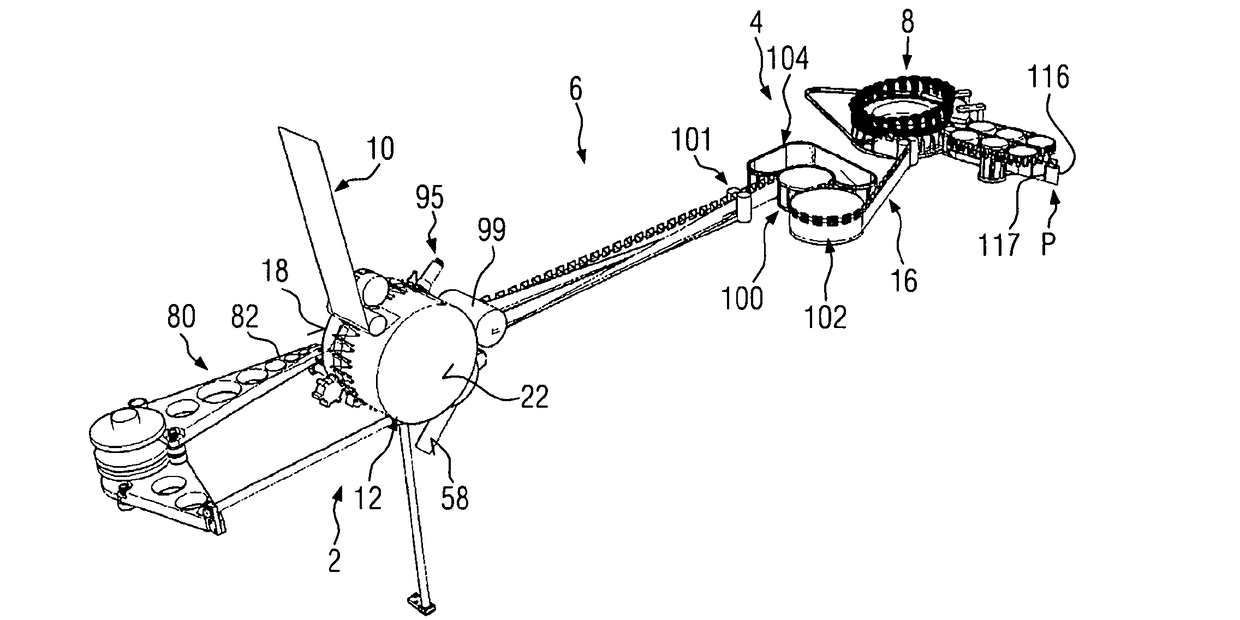
[0041]FIG. 1 shows an embodiment of an apparatus suitable for conducting the inventive method. This apparatus comprises a web preparation module 2, a vertical sealer module 4, a folding module 6 arranged between the web preparation module 2 and the vertical sealer module 4 and a filler module 8 arranged behind the vertical sealer module 4 in the travelling direction of a web.

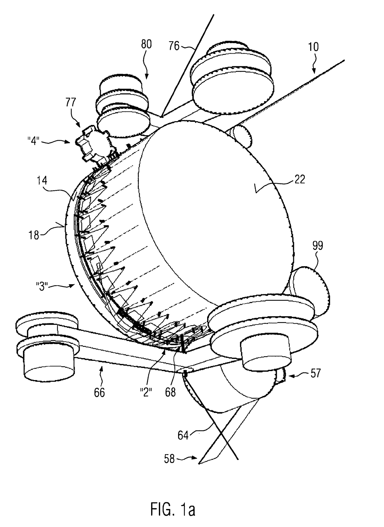
[0042]This web is fed to the web preparation module 2 as a continuous, unfolded web 10, the central part thereof being formed by a drum 12, which is rotatably driven in clockwise direction when viewed in accordance with the representation of FIG. 1. The flat projection of an outer circumferential surface 14 of the drum 12 as depicted in FIG. 2 to elucidate the essential steps of preparing the unfolded web 10 prior to folding in the folding module 6.

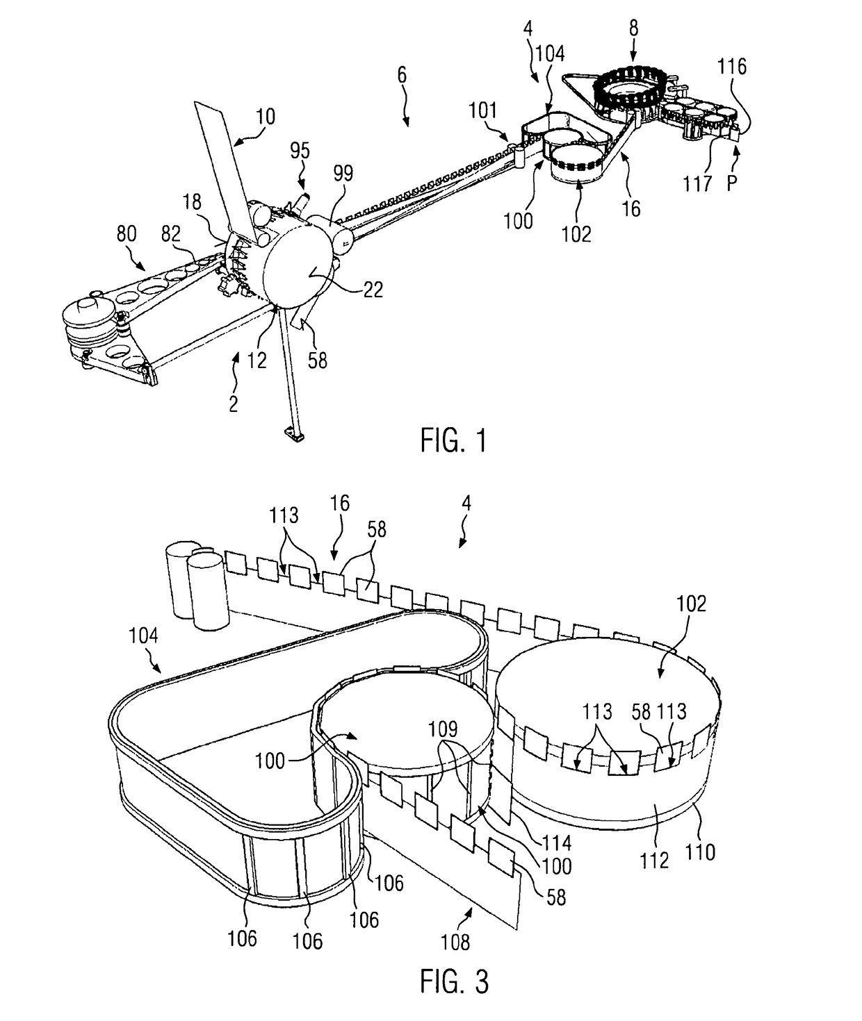
[0043]In FIG. 2, dotted lines identify various stations of pouches to be formed, which pouches are made by cutting a pouch train identified with reference numeral 16 ...


PUM

PropertyMeasurementUnit
angleaaaaaaaaaa
temperatureaaaaaaaaaa

Abstract

The present invention relates to a pouch and a method for making the same. In the inventive method, which is adapted to produce pouches having a limited amount of fusible material, a heat-sealable cord is arranged on a web forming confronting side surface of each pouch. Those confronting side surfaces are fused by heating the heat-sealable cord. The present invention furthermore provides a pouch, in particular containing a brewable or extractable commodity such as tea, with a pocket defined between confronting side surfaces of a web. The pouch of the present invention can have a limited amount of fusible material as the confronting side surfaces are joined by solidified melt of a heat-sealable cord arranged in vicinity of at least one edge of the pouch.

Description

CROSS REFERENCE TO RELATED APPLICATIONS[0001]This application is the national stage application of International patent application No. PCT / EP2012 / 004081, entitled “A Method for Making Pouches and a Pouch as Such,” and filed on Sep. 28, 2012, which claims priority to European application No. 12000884.2, entitled “A Method for Making Pouches and a Pouch as Such” and filed on Feb. 10, 2012, which are hereby incorporated by reference herein in their entireties.BACKGROUND OF THE INVENTION[0002]A method for producing pouches comprising the steps of providing a continuous web, folding the web to provide confronting side surfaces joined along a bottom edge and forming a vertical seal between the confronting side surfaces, thereby providing a series of adjacent pockets having opposite side walls, with each pocket having an unsealed opening along a top edge, and filling the pockets through the opening with material and then sealing the opening to provide sealed pouches is known from WO 2007 / ...

Claims


Application Information

Patent Timeline
Patent Type & Authority Patents(United States)
IPC IPC(8): B65B29/04B65B29/02B29C65/40B65D85/808B65D33/14
CPCB65B29/02B65B29/04B65D85/808B65D33/14B29C65/40
Inventor LAMBERTZ, STEFANHADDOW, PHILWHITLOCK, PETER JOHNWIGGETT, BRADLEYKLEIN, MICHAELKNOPS, HANSREICHEL, WOLFGANG
Owner TEEPACK SPEZIALMASCH
Why Eureka
Try Eureka