Coupling device

a technology of coupling device and actuating clutch, which is applied in the direction of electrically actuated clutches, non-mechanical actuated clutches, interengaging clutches, etc., can solve the problems of constant relative movement, increased wear, and ensuing maintenance effort, and achieves simple and cost-effective effects, reducing costs, and reducing costs

Inactive Publication Date: 2018-04-03
SIEMAG TECBERG
View PDF23 Cites 0 Cited by
  • Summary
  • Abstract
  • Description
  • Claims
  • Application Information

AI Technical Summary

Benefits of technology

[0013]It is therefore the object of the present invention to provide a coupling device of the generic type which avoids the stated disadvantages of known devices, which is as easily as possible to realize and which makes possible low-maintenance, safe and cost-effective operation.
[0015]The advantages of this arrangement are that no separate adjusting collar or ring is required any longer and fewer masses have to be moved. Further advantages lie in the substantially lower wear due to the selective actuation and in that existing installations can be easily retrofitted.
[0017]The small number of actuating means makes the installation easy to assemble and maintain.
[0018]It is further preferred that the actuating means are stationary and the sliding wheel can rotate past and over the former, such that the moved masses can be kept to a minimum.
[0020]On at least one of their inner sides facing the circumferential flange the claws can be supplied with a rubber buffer which comes into contact with the circumferential flange upon engaging and / or disengaging. More preferably that inner side of the claw is supplied with a rubber buffer, which, upon engagement of the sliding wheel, comes into contact with the flange of the former. In this fashion, the engaging forces can be reduced by soft engagement.
[0022]Finally, in a preferred embodiment the coupling device can also be configured such that the sliding wheel is supplied with tooth segments distributed over the outer and inner circumference instead of a respective complete circumferential toothing, for engagement with corresponding outer and inner toothings on the loose drum and the shaft wheel. In a further preferred embodiment, these tooth segments can also be configured as separate elements that can be incorporated in and detached from the sliding wheel and which can be connected thereto in force-fitting and / or form-fitting fashion. This solution makes it possible to exchange worn tooth segments in a simple and cost-effective fashion without having to exchange the complete coupling wheel or sliding wheel at once. The use of tooth segments instead of a complete toothing on the outer circumference of the sliding wheel consequently reduces the costs considerably.

Problems solved by technology

It is disadvantageous in this arrangement that relative movements always occur between the stationary displacement collar / adjusting ring and the rotating coupling wheel during the normal hoisting operation.
These relative movements lead to wear and ensuing maintenance effort.
Further, these points represent potential disturbances.
The relative movement also has a negative effect on the heating and the ensuing deformation of the components, additionally increasing the wear.

Method used


Image

  • Coupling device
  • Coupling device
  • Coupling device

Examples


Embodiment Construction

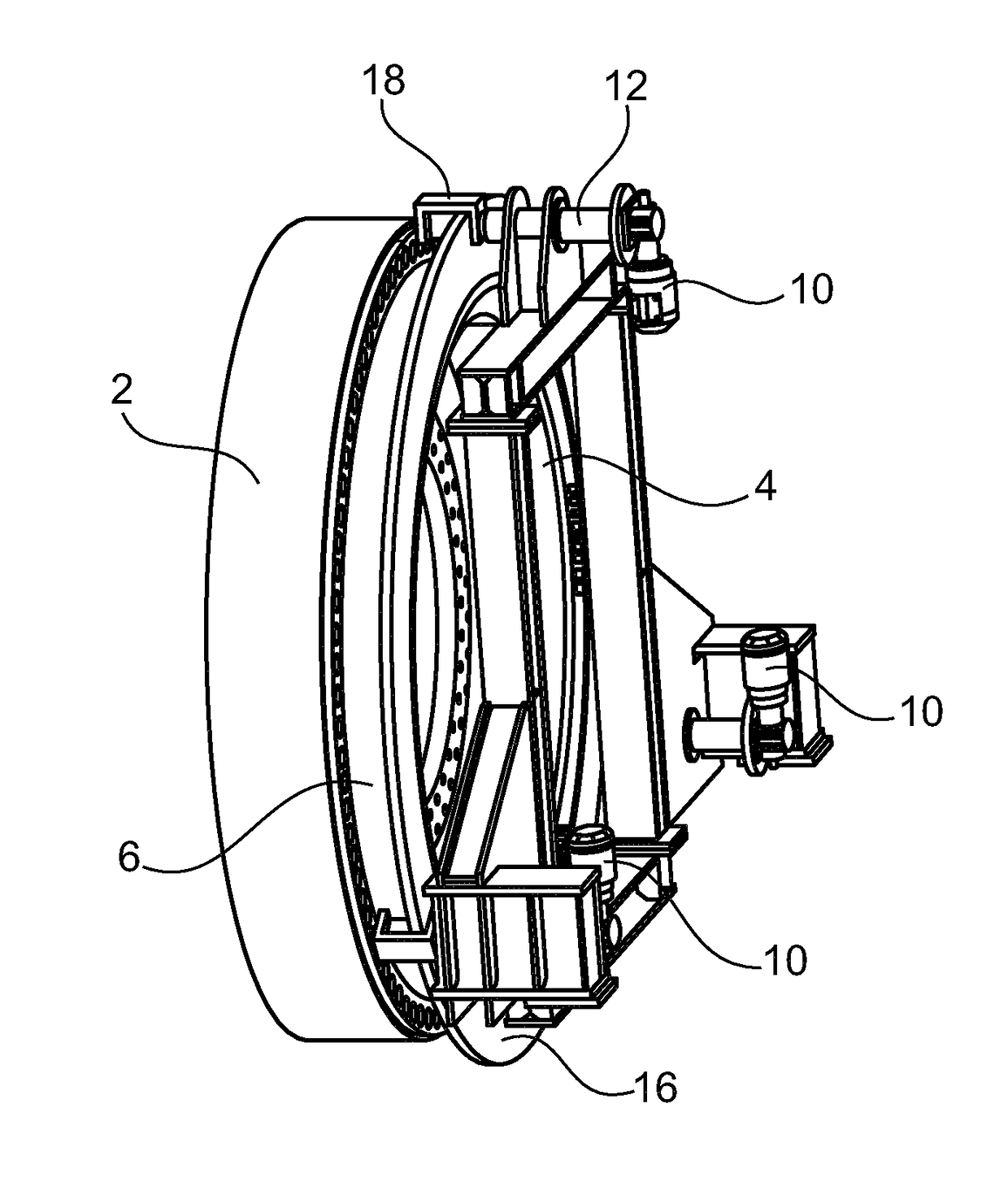
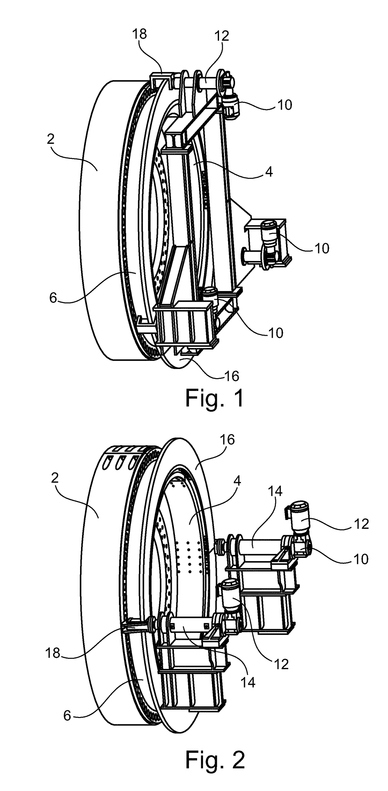
[0028]FIGS. 1 and 2 show two preferred embodiments of a coupling device according to the present invention. Both figures show the coupled state of the coupling device. Corresponding elements also bear the corresponding reference numbers.

[0029]From FIGS. 1 and 2 the drum wheel 2 of a double-drum hoisting machine can be gathered in each case, and a corresponding shaft wheel 4 connected to a (not shown) main shaft of the double-drum hoisting machine.

[0030]Further, from FIGS. 1 and 2 also a coupling or sliding ring 6 can be gathered, which in the present case is guided via an outer toothing of the shaft wheel 4 and a corresponding inner toothing on the sliding ring 6.

[0031]Likewise, from FIGS. 1 and 2 actuating means 10 distributed over the circumference of the sliding ring 6 can be gathered, wherein in the case of FIG. 1 there are provided three and in the case of FIG. 2 there are provided two actuating means 10. In the represented embodiments of the coupling device the actuating means...


PUM


Abstract

The invention relates to a plugging device for releasably connecting the drum wheel (2) of the at least one loose drum rotatably mounted on the main shaft of a winding engine, said drum wheel being rigidly connected to the loose drum, to the shaft wheel (4) which is rigidly connected to the main shaft. The releasable connection of the drum wheel (2) to the shaft wheel (4) is carried out in a formfitting manner by means of an engageable and disengageable sliding wheel (6) which is guided on a shaft wheel (4). Actuations (10) are carried out in points in a distributed manner over the circumference of the sliding wheel, said actuations acting directly on the sliding wheel (6), in order to engage and disengage the sliding wheel (6).

Description

BACKGROUND OF THE INVENTION[0001]Field of the Invention[0002]The present invention relates to a coupling device for hoisting machines.[0003]Brief Description of the Related Art[0004]In the shaft and inclined hoisting technology, so-called double-drum hoisting machines or double-drum Blair hoisting machines are used at small depths of up to 500 m and at great depths of 1,750 m to 3,000 m, said hoisting machines counteractively coiling and / or uncoiling one or two ropes per drum.[0005]As a rule, at least one of the drums is configured as a loose drum and the other possibly as a fixed drum. The loose drum which is rotatably mounted on the main shaft via sliding bushings or rolling bearings is connected to the main shaft with a coupling device.[0006]This coupling device must be configured as a switchable clutch (coupling and uncoupling) in order to be able to move the two drums relative to each other at any given time in standstill with engaged loose-drum brake.[0007]In the course of the...

Claims


Application Information

Patent Timeline
Patent Type & Authority Patents(United States)
IPC IPC(8): B66D1/16B66D1/26F16D11/14F16D28/00F16D11/00
CPCB66D1/16B66D1/26F16D28/00F16D11/14F16D2011/004
Inventor SONNEBORN, STEPHAN
Owner SIEMAG TECBERG
Why Eureka
Try Eureka