Method and system of measurement of mach and dynamic pressure using internal sensors

a technology of dynamic pressure and internal sensors, applied in the direction of fluid speed measurement, fluid speed measurement using pressure difference, instruments, etc., can solve the problems of inconvenient extension of these tubes into the free airstream, performance starts to suffer, and time schedules are difficult to predi

Active Publication Date: 2018-04-03
BAE SYST INFORMATION & ELECTRONICS SYST INTERGRATION INC
View PDF2 Cites 2 Cited by
  • Summary
  • Abstract
  • Description
  • Claims
  • Application Information

AI Technical Summary

Problems solved by technology

The extension of these tubes into the free airstream can be an inconvenience, particularly in rocket and munition applications.
In addition, the tube can become clogged with debris impacting the accuracy of the measurements from which one can calculate gains for an autopilot.
However, if these autopilots are employed on munition fired from a fixed wing aircraft or jet aircraft flying at Mach speed, then a very dynamic condition may be obtained for which a time schedule is hard to predict, especially one that fits a range of platforms including both helicopters and jet aircraft.
However, the fact is that as time goes on, deviation further and further from the trajectory assumption occurs, and performance starts to suffer.
Moreover, for certain types of munitions the rocket or projectile is launched almost vertically and the time variation of the sequence of dynamic pressure and gain is a complicated process to predict.
However these pitot tubes and other sensors that project beyond the skin of the munition or vehicle oftentimes produce unreliable results.
Moreover, sensors mounted to the exterior of a munition can be damaged in transport or during launch under a high G environment.
Moreover, when a rocket is launched out of a tube, with a neighboring rocket launched just before, the adjacent rocket is subjected to a backwash of exhaust fumes that can potentially clog the pitot tube and therefore change its performance characteristic.
Thus, a heretofore unaddressed need exists in the industry to address the aforementioned deficiencies and inadequacies.

Method used


Image

  • Method and system of measurement of mach and dynamic pressure using internal sensors
  • Method and system of measurement of mach and dynamic pressure using internal sensors
  • Method and system of measurement of mach and dynamic pressure using internal sensors

Examples


Embodiment Construction

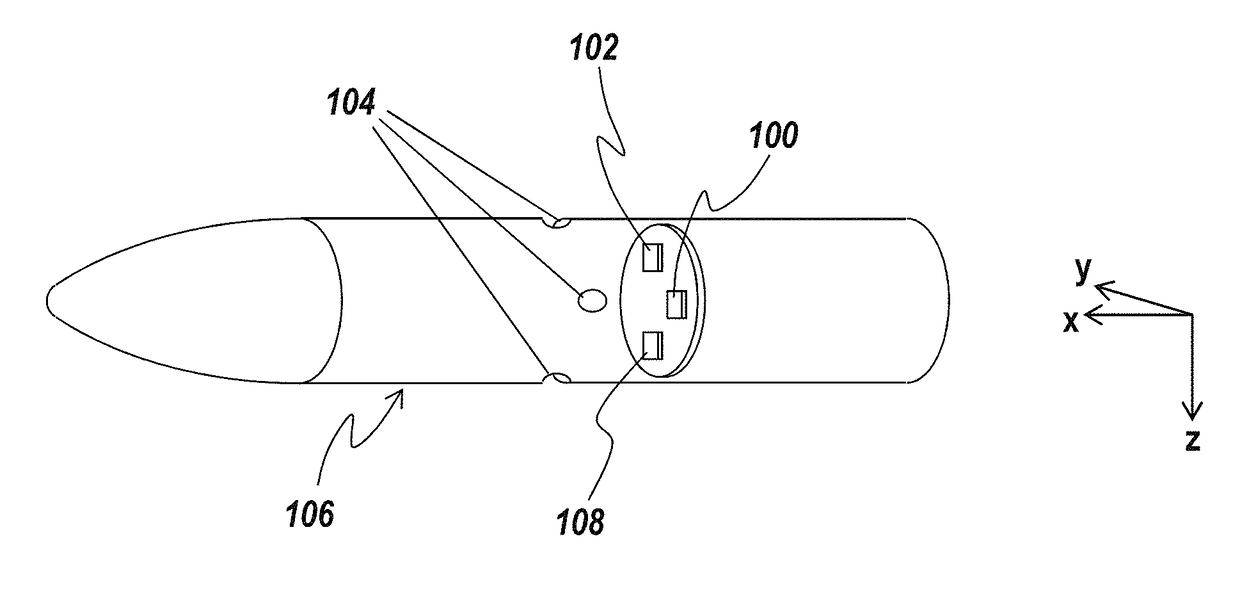
[0025]It is the subject of the present invention to use internal sensors to establish dynamic pressure by measuring pressure internal to the munition as well as axial acceleration. By so doing, it is possible to establish Mach numbers and velocity critical to setting autopilot gain without having to measure dynamic pressure exterior to the vehicle or munition. Thus, sensors extending beyond the skin of the munition are not required. As a result, sensors to establish Mach number and velocity are maintained within the body of the vehicle without any need for extension outside in the airstream.

[0026]More specifically, this invention provides the means to measure dynamic pressure and Mach velocity using internal sensors. Dynamic pressure and Mach number are key parameters in the control of the airframe as variation in these two parameters dominate the time varying response of the system. Knowledge of dynamic pressure and Mach number permit implementation of an adaptive control system al...


PUM


Abstract

A system for calculating airspeed and dynamic pressure comprises a system body, an internal accelerometer, located within the system body, an internal pressure sensor, located in the system body, the internal pressure sensor being not hermetically sealed within the system body and capable of measuring the static pressure of the ambient atmosphere, and a processor in reception of the internal accelerometer, and the internal pressure sensor, capable of calculating Mach number via an axial acceleration, and capable of calculating a dynamic pressure and a true airspeed via the Mach number.

Description

CROSS REFERENCE TO RELATED APPLICATION[0001]This application claims benefit of U.S. Provisional Application Ser. No. 62 / 033,194 entitled, “Method and System of Measurement of Mach and Dynamic Pressure using Internal Sensors” filed Aug. 5, 2014, the entire disclosure of which is incorporated herein by reference.STATEMENT OF GOVERNMENT INTEREST[0002]This invention was made with United States Government support under Contract No. N00019-11-C-0033 awarded by the Dept. of the Navy. The United States Government has certain rights in this invention.FIELD OF THE INVENTION[0003]The present invention relates to autopilot control of munitions such as missiles and other ordinance and more particularly to the measurement of Mach number and dynamic pressure utilizing sensors solely within the missile or ordinance.BACKGROUND OF THE INVENTION[0004]Mach number, dynamic pressure and airspeed are typically used to set the gain of autopilots and measuring these parameters typically relies on devices th...

Claims


Application Information

Patent Timeline
Patent Type & Authority Patents(United States)
IPC IPC(8): G01P5/14G01P5/02G01P15/00
CPCG01P5/14G01P5/02G01P15/00
Inventor FREY, JR., ROBERT D.SCHORR, DAVID J.
Owner BAE SYST INFORMATION & ELECTRONICS SYST INTERGRATION INC
Why Eureka
Try Eureka