Method and magnetic resonance apparatus for determination of excitation profiles from excitation pulses

a technology of excitation pulse and magnetic resonance, applied in the direction of magnetic measurement, measurement using nmr, instruments, etc., can solve the problem of inability to select specific slices, and achieve the effect of simple and fast determination of excitation profiles

Active Publication Date: 2018-04-03
SIEMENS HEALTHCARE GMBH
View PDF7 Cites 3 Cited by
  • Summary
  • Abstract
  • Description
  • Claims
  • Application Information

AI Technical Summary

Benefits of technology

[0009]An object of the present invention is to provide a simple and fast determination of excitation profiles from excitation pulses in magnetic resonance, which can easily be performed on different existing magnetic resonance systems.
[0016]The procedure according to the invention allows for a quick determination of excitation profiles with very high precision, which can easily be performed with different magnetic resonance systems. The saved excitation profiles can easily be integrated into the above mentioned correction procedure, suitable for every magnetic resonance system.
[0018]By averaging individual intensity profiles of the measured data sets are in the determination of the intensity profile, a particularly high accuracy can be accomplished and it is possible to achieve a lower susceptibility to coil intensity, excitation differences.

Problems solved by technology

A specific slice selection is not possible; rather, an undesired slice selection is performed by the activated gradient at the time of the excitation, when the object that is to be measured is superimposed with the excitation profile of the pulse.

Method used


Image

  • Method and magnetic resonance apparatus for determination of excitation profiles from excitation pulses
  • Method and magnetic resonance apparatus for determination of excitation profiles from excitation pulses
  • Method and magnetic resonance apparatus for determination of excitation profiles from excitation pulses

Examples


Embodiment Construction

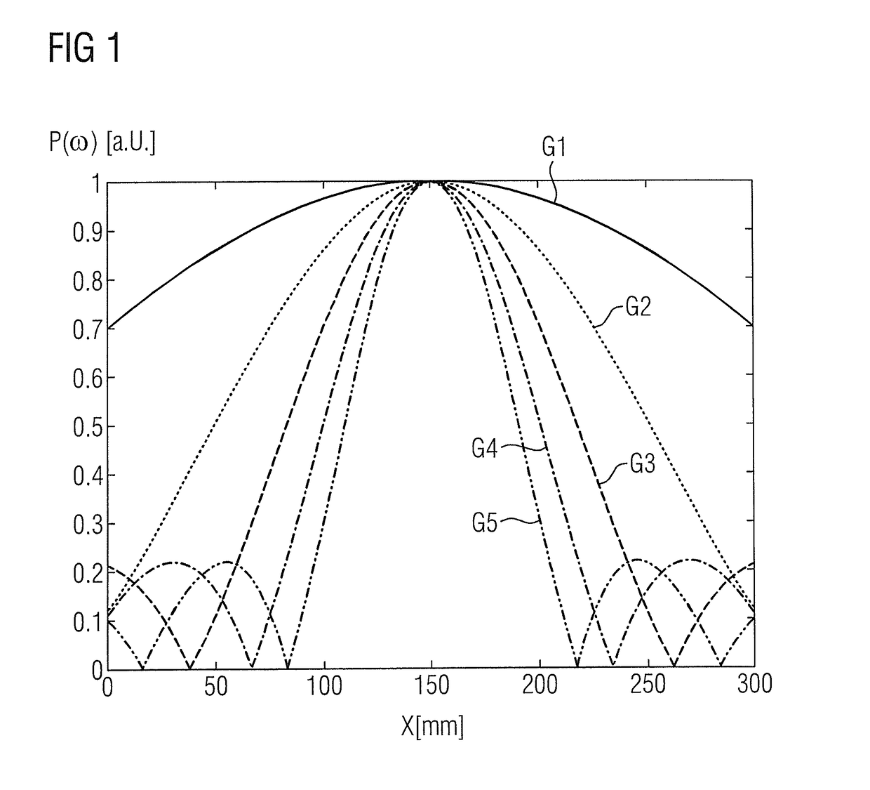
[0026]As an example, FIG. 1 illustrates the dependency of the excitation profile in x-direction (in millimeter “mm”) and thus of the effected excitation P(k,x) (in arbitrary units “a.u.”) to a momentarily applied gradient strength G1, G2, G3, G4, G5. In the given example G5>G4>G3>G2>G1. As can be seen, the excitation profile becomes wider as the applied gradient strength is decreased. The widest excitation profile (depicted with a continuous line), which means an excitation (P(k,x)) that is as homogeneous as possible, stretching over the largest spatial area (x), is thus achieved at G1. The narrowest excitation profile (depicted with a double dotdashed line), which already accomplishes a significant change in the excitation (P(k,x)) at a low spatial change (x), is achieved at G5.

[0027]In general, the excitation profile of an excitation pulse theoretically corresponds to the Fourier-transformation of the pulse-shape of the excitation pulse in the time and space domain p(t). In the ex...


PUM


Abstract

In a method for determining excitation profiles from excitation pulses in a magnetic resonance, a homogeneous phantom is placed within the measurement volume of the magnetic resonance apparatus, at least one measurement data set of the phantom is acquired by operating the apparatus with a test pulse sequence composed of one excitation pulse, of which the excitation profile is to be determined, and a test gradient that is already activated on at full strength while the excitation pulse (A) is irradiated. The intensity profile of at least one acquired measurement data set in the direction in which the test gradient was switched on is determined in a processor, and the excitation profile of the excitation pulse is determined from the calculated intensity profile. The determined excitation profile is saved.

Description

BACKGROUND OF THE INVENTION[0001]Field of the Invention[0002]The invention refers to the determination of excitation profiles from excitation pulses in magnetic resonance.[0003]Description of the Prior Art[0004]Magnetic resonance (MR) technology (also called magnetic resonance imaging), is a well-known modality, with which images can be made of the inside of an object under examination. In simple terms, the object under examination is positioned in a magnetic resonance device in a relatively strong static, homogeneous basic magnetic field, also called B0-field, with field strengths ranging from 0.2 Tesla to 7 Tesla and more, so that nuclear spins in the subject are aligned along the basic magnetic field. In order to trigger nuclear spin resonances, radio-frequency excitation pulses (RF-pulses) are irradiated, and the triggered nuclear spin resonances are measured as so-called k-space data and MR-images are reconstructed or spectroscopic data are determined from the k-space data. For...

Claims


Application Information

Patent Timeline
Patent Type & Authority Patents(United States)
IPC IPC(8): G01R33/32G01R33/54G01R33/24G01R33/483G01R33/58
CPCG01R33/32G01R33/246G01R33/583G01R33/54G01R33/4833
Inventor GRODZKI, DAVID
Owner SIEMENS HEALTHCARE GMBH
Why Eureka
Try Eureka