Method for Operating an Internal Combustion Engine

Active Publication Date: 2008-07-31
ANDREAS STIHL AG & CO KG
View PDF25 Cites 12 Cited by
  • Summary
  • Abstract
  • Description
  • Claims
  • Application Information

AI Technical Summary

Benefits of technology

[0003]It is an object of the present invention to provide a method for operating an internal combustion engine, in which engine a pre-igni

Problems solved by technology

This requires a comparatively comp

Method used


Image

  • Method for Operating an Internal Combustion Engine
  • Method for Operating an Internal Combustion Engine
  • Method for Operating an Internal Combustion Engine

Examples


Embodiment Construction

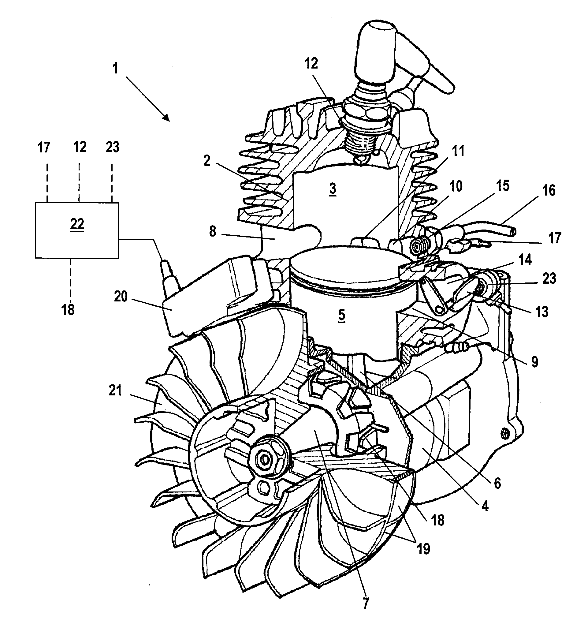
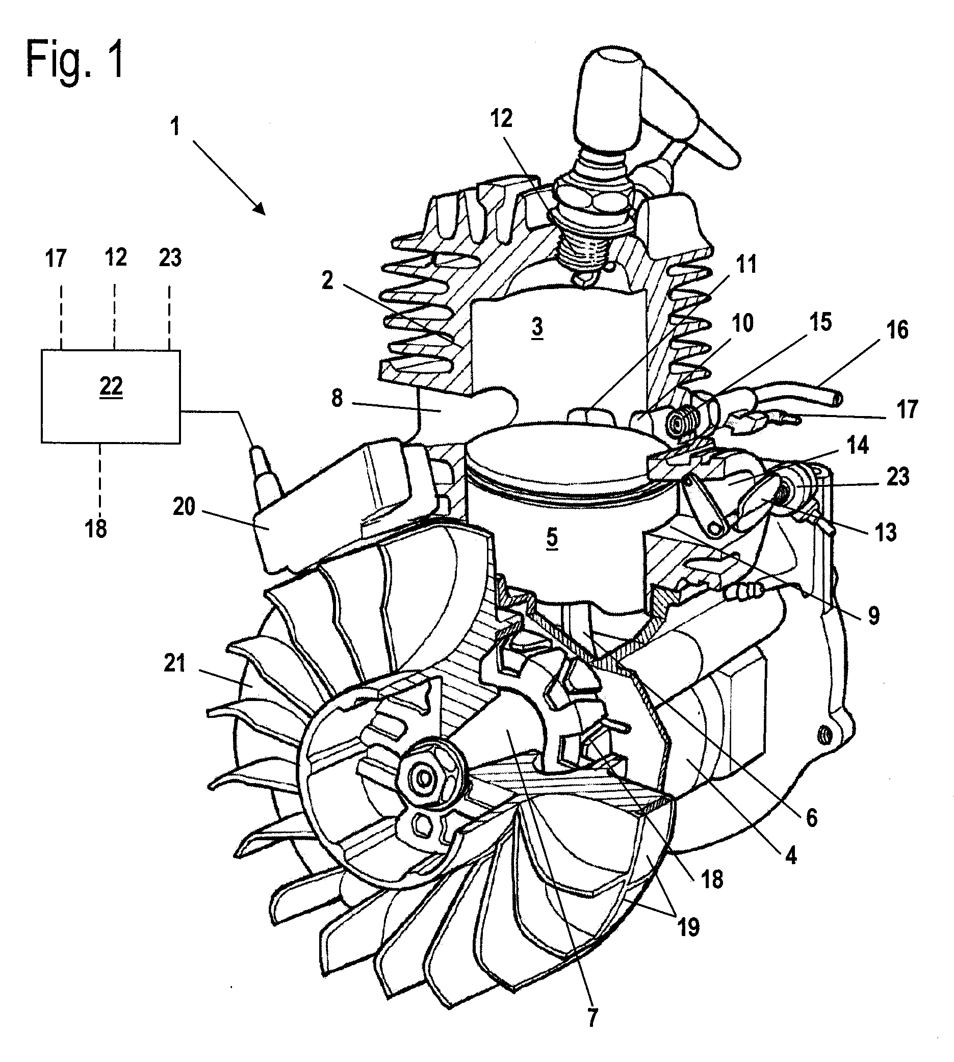
[0026]The internal combustion engine 1 illustrated in FIG. 1 is a single cylinder engine. The internal combustion engine 1 is a two-stroke engine that is provided in particular for driving a tool of a hand-held power tool such as a motor chainsaw, a cut-off machine, a trimmer or the like. The method according to the invention can also be used in a four-stroke engine. The internal combustion engine 1 comprises a cylinder 2 in which a combustion chamber 3 is provided. The combustion chamber 3 is delimited by a piston 5 supported so as to reciprocate within the cylinder 2. By means of a connecting rod 6, the piston 5 drives in rotation a crankshaft 7 rotatably supported in the crankcase 4. A fan wheel 21 is fixedly connected to the crankshaft 7. The fan wheel 21 supports the pole shoes 19 that generate in an ignition module 20 arranged at the circumference of the fan wheel 21 a voltage for a spark plug. In the area of the fan wheel 21 an alternator 18 is arranged on the crankshaft 7. I...


PUM


Abstract

In a method for operating an internal combustion engine, wherein the internal combustion engine has a cylinder in which a combustion chamber is provided that is delimited by a reciprocating piston guided in the cylinder, wherein the piston is connected by a connecting rod to a crankshaft and wherein the internal combustion engine has a device for supplying fuel and a device for igniting the fuel/air mixture in the combustion chamber at least one engine speed value of the internal combustion engine is determined and evaluated. A pre-ignition state of the internal combustion engine is determined based on the result of the evaluation step.

Description

BACKGROUND OF THE INVENTION[0001]The invention relates to a method for operating an internal combustion engine in which a glow ignition state (pre-ignition state) of the internal combustion engine is determined. The internal combustion engine comprises a cylinder in which a combustion chamber is provided that is delimited by a reciprocating piston guided in the cylinder wherein the piston is connected by a connecting rod to a crankshaft and wherein the internal combustion engine has a device for supplying fuel and a device for igniting the fuel / air mixture in the combustion chamber.[0002]U.S. Pat. No. 5.526,788 discloses a method for determining a glow ignition state (pre-ignition state) of the internal combustion engine. In this method, the spark plug is utilized for determining the pre-ignition state. For this purpose, the current supply to the spark plug is measured and evaluated. This requires a comparatively complex electronic evaluation circuit.SUMMARY OF THE INVENTION[0003]It...

Claims


Application Information

Patent Timeline
IPC IPC(8): F02D45/00
CPCF02D41/1498F02D2400/04F02D2200/1012
Inventor NAEGELE, CLAUSNICKEL, HANSNICKEL, BARBEL
Owner ANDREAS STIHL AG & CO KG
Why Eureka
Try Eureka