
Compressor with thrust balancing and method thereof

a compressor and thrust technology, applied in the direction of pump control, liquid fuel engine components, non-positive displacement fluid engines, etc., can solve the problems of limiting the thrust compensation, not being able to compensate the thrust, and insufficient thrust bearings, so as to increase the thrust range and increase the flow rate range

Active Publication Date: 2018-04-10
THERMODYN
View PDF43 Cites 3 Cited by
  • Summary
  • Abstract
  • Description
  • Claims
  • Application Information

AI Technical Summary

Benefits of technology

This configuration enhances the thrust range and flow rate capabilities of the compressor, ensuring effective thrust compensation and preventing damage to seals and bearings, even at high flow rates, by achieving pressure equilibrium and recycling gases.

Problems solved by technology

In certain specific cases of compressors, such as, for example, compressors with a wide flow rate range, that is to say with a high flow rate coefficient, the thrust bearing is not sufficient.
However, this solution does not make it possible to compensate the thrust in the case of high gas flow rate.
In practice, even with the control valve closed on the balancing line, it is not possible to reach the discharge pressure in the rear cavity of the piston, which results in a limiting of the thrust compensation.

Method used


Image

  • Compressor with thrust balancing and method thereof
  • Compressor with thrust balancing and method thereof

Examples


Embodiment Construction

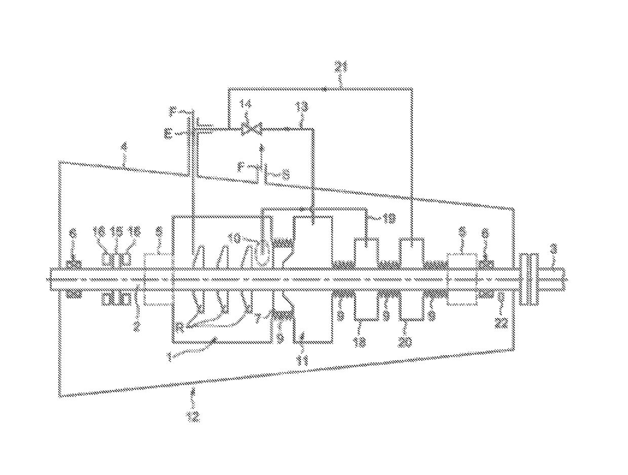
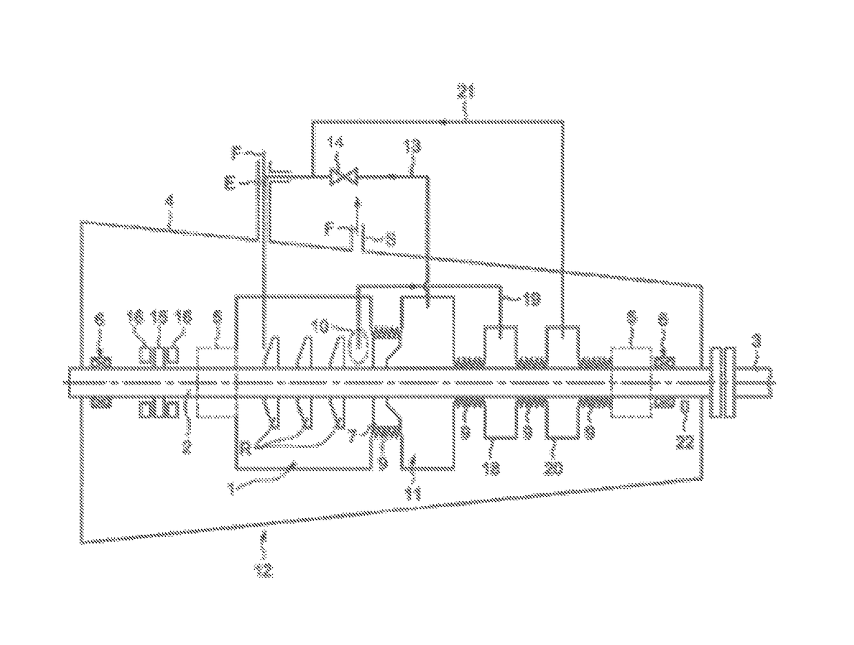
[0022]In the exemplary embodiment illustrated, the compressor is a compressor in which the compression section 1 comprises a set of compression bladed wheels R ensuring the compression of a gas delivered at the input E of the compressor to deliver at the output S the gas manipulated by the compressor (arrows F).

[0023]The bladed wheels R are mounted on a driven shaft 2 driven in rotation by a motor shaft 3.

[0024]The compression section 1 of the compressor is placed, in the embodiment illustrated, in a compressor jacket 4 kept seal-tight by virtue of sealing means 5 arranged on either side of the compressor jacket along the driven shaft 2. The sealing means 5 can be dry packings comprising, among other things, a system of cavities separated by seals, for example labyrinth seals.

[0025]The compressor also comprises bearings 6, here two of them, making it possible to support the driven shaft 2. The bearings 6 can be magnetic bearings. The bearings 6 can also be oil bearings, in which cas...


PUM


Abstract

A compressor for a motor-compressor set, comprising, on a rotating shaft, a balancing piston, a set of bladed wheels, a rear cavity of the piston adjacent to the balancing piston on a side opposite to the set of bladed wheels, a regulation valve suitable for coupling the rear cavity to the input of the set of bladed wheels, a suction pressure chamber coupled to the input of the set of bladed wheels, the rear cavity being arranged between the balancing piston and the suction pressure chamber. The compressor comprises a discharge pressure chamber arranged between the rear cavity of the piston and the suction pressure chamber, the discharge pressure chamber being coupled via a discharge line to a discharge area between the set of bladed wheels and the balancing piston.

Description

BACKGROUND[0001]Embodiments of the present invention relate generally to the balancing of the thrust exerted in a centrifugal compressor, and more particularly to improving the maximum thrust that the architecture of a centrifugal compressor can withstand.[0002]In operation, the rotor of a centrifugal compressor is generally subjected to significant thrusts. These thrusts are due to the pressure difference prevailing between the stages and to the quantity of movement created by the change of direction of the gas, from an axial direction to a radial direction. The flow rate tends to generate a thrust directed from the suction to the discharge of the compressor. The pressure difference at the limits of each wheel thrusts in the opposite direction.[0003]The compensation of such a phenomenon is generally carried out by using a balancing piston which acts in the same direction as the thrust due to the flow rate. Bearing in mind that the compressor is likely to operate in various conditio...

Claims


Application Information

Patent Timeline
Patent Type & Authority Patents(United States)
IPC IPC(8): F04D29/051F04D29/12F04D27/02
CPCF04D29/0513F04D29/124F04D29/0516F04D27/02F04D29/051
Inventor STALDER, BENJAMINALBAN, THOMAS
Owner THERMODYN
Learn More