Pre-match prediction for pattern testing

a pattern and prediction technology, applied in matching and classification, instruments, computing, etc., can solve the problems of reducing the speed and accuracy trade-offs of lower cost systems, and comparing performance with performance, so as to speed up the process and quickly confirm the

Active Publication Date: 2018-04-10
IDEX BIOMETRICS ASA
View PDF59 Cites 1 Cited by
  • Summary
  • Abstract
  • Description
  • Claims
  • Application Information

AI Technical Summary

Benefits of technology

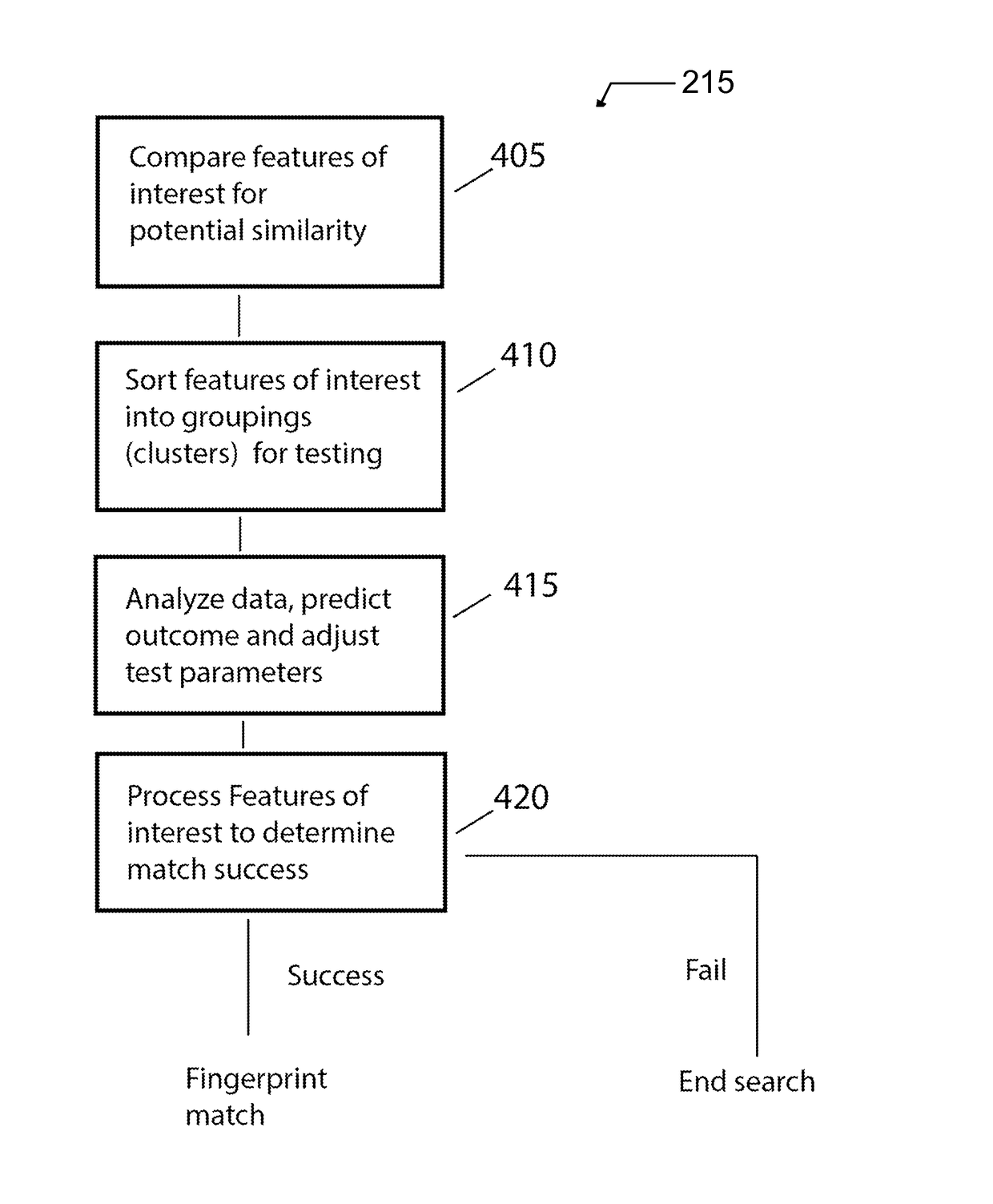
[0013]Based upon several factors during the pre-match processing, the pre-match phase may predict a match. In such a case, some embodiments of the present invention may predict a match with enough confidence that the match phase may be used as a “sanity” check to determine whether the predicted match is a rational or reasonable conclusion. While a normal match phase may be employed, alternatively and preferably some aspect of the match phase may be made less rigorous or less onerous. This may be done by lowering a threshold required to pass, decreasing a number of successes required to pass, allowing a greater number of fails before concluding no match, and / or otherwise making the match phase easier for a positive determination of a match condition between the sample pattern and the reference pattern. In one sense, the pre-match phase evaluation suggests that it is improbable, to some level of confidence, that the sample pattern will not match the test pattern when the match process is performed. The prediction of a pass is used in these embodiments to speed up the process by quickly confirming the pre-test prediction.
[0014]In other cases, the pre-match phase may predict a non-match. In such a case, some embodiments of the present invention may predict a failed match with enough confidence that the match phase may be used as a final check to prove the pre-match prediction was in error and that there should be a match in spite of the predicted failure mode. While a normal match test may be employed, alternatively and preferably in some embodiments, some aspect of the match phase may be made more rigorous or onerous. This may be done by increasing a threshold required to pass, increasing a number of successes required to pass, allowing a lesser number of fails before concluding no match, and / or otherwise making the match phase more difficult for a positive determination of a match condition between the sample pattern and the reference pattern.

Problems solved by technology

Adoption of patterning devices, for example, fingerprint sensors, in consumer systems is influenced by user costs.
The costs are not just the retail price of the consumer system with a fingerprint sensor, but also performance in terms of speed, accuracy, and convenience of the features implemented by the fingerprint sensor.
There is a natural tension in terms of cost versus performance in that lower cost systems may offer decreased speed and accuracy trade-offs.

Method used


Image

  • Pre-match prediction for pattern testing
  • Pre-match prediction for pattern testing
  • Pre-match prediction for pattern testing

Examples


Embodiment Construction

[0029]Embodiments of the present invention provide a system and method for improving speed of automated pattern testing for any particular hardware configuration. The following description is presented to enable one of ordinary skill in the art to make and use the invention and is provided in the context of a patent application and its requirements.

[0030]Various modifications to the preferred embodiment and the generic principles and features described herein will be readily apparent to those skilled in the art. Thus, the present invention is not intended to be limited to the embodiment shown but is to be accorded the widest scope consistent with the principles and features described herein.

Definitions

[0031]Unless otherwise defined, all terms (including technical and scientific terms) used herein have the same meaning as commonly understood by one of ordinary skill in the art to which this general inventive concept belongs. It will be further understood that terms, such as those def...


PUM


Abstract

A system and method for improving speed of automated pattern testing for any particular hardware configuration. A pattern testing includes a matching process and a pre-match process that establishes features of interest used in the match process. The pre-match process is used to predict a likelihood of a passed match (or a failed match) and alters the subsequent match process in response to the prediction.

Description

CROSS REFERENCE TO RELATED APPLICATIONS[0001]This application claims benefit of U.S. Provisional Application No. 62 / 126,140 filed 27 Feb. 2015, the contents of which are hereby expressly incorporated by reference there to it is entirety for all purposes.FIELD OF THE INVENTION[0002]The present invention relates generally to automatic machine-implemented pattern testing, and more specifically, but not exclusively, to systems, methods, and computer program products for automated pre-match predictions of pattern matching, such as, for example, fingerprint verification or other biometric pattern testing.BACKGROUND OF THE INVENTION[0003]The subject matter discussed in the background section should not be assumed to be prior art merely as a result of its mention in the background section. Similarly, a problem mentioned in the background section or associated with the subject matter of the background section should not be assumed to have been previously recognized in the prior art. The subj...

Claims


Application Information

Patent Timeline
Patent Type & Authority Patents(United States)
IPC IPC(8): G06K9/00G06K9/68
CPCG06K9/00087G06K9/001G06K9/685G06K9/00067G06K9/0008G06V40/1359G06V40/1376G06V30/248G06V40/1365G06V40/1347
Inventor BAUCHSPIES, ROGER A.
Owner IDEX BIOMETRICS ASA
Why Eureka
Try Eureka