Motorized wheel assembly

a technology for motorized wheels and assemblies, applied in the direction of battery/cell propulsion, electric devices, sport apparatus, etc., can solve the problems of restricting the use of these assemblies, and achieve the effect of reducing weight and cos

Active Publication Date: 2018-04-24
SARGIS RAMAN
View PDF21 Cites 22 Cited by
  • Summary
  • Abstract
  • Description
  • Claims
  • Application Information

AI Technical Summary

Benefits of technology

[0013]The motorized wheel assembly combined with an adaptable weight transfer assembly is used to motorize a common skateboard using a separate motorized wheel. The motorized front wheel assembly is self-contained with battery pack, electric motor, control electronics, charging port, handle bars, braking system, and the weight transfer assembly required to attach to a skateboard. The motorized wheel assembly construction does not have to be as heavy-duty as those used for electric skateboards in the art. For example, the motorized wheel assembly attached to a skateboard, carries only a fraction of rider's weight since the existing skateboard wheels bear the direct weight of the rider due to their position under the skateboard. Furthermore, for an embodiment of the motorized wheel assembly, the rider's weight transfer to the motorized wheel assembly is through embodiments of the weight transfer assembly providing at least one compression spring. The skateboard rider's weight is transferred to, and distributed among, the skateboard wheels and the motorized wheel to establish motorized wheel traction. Thus, the motorized wheel assembly can use light duty components for normal rider usage, which reduces weight and cost. Similar weight transfer dynamics are presented by alternate embodiments having at least one shock absorber to provide a range of motion for the front end of the skateboard once it is attached to the motorized wheel assembly.

Problems solved by technology

Disadvantages of the present state of the art include: 1) the motor and battery greatly reduce clearance under the board or scooter deck causing unintentional scraping of components when riding over obstacles or uneven surfaces and thus limiting the use of these assemblies to well paved surfaces; 2) the motor and battery pack require protective shielding against unintentional and harsh bumping and scraping; and 3) all the motor elements are pre-integrated into the structure of the board or scooter which limits usage to a single board or scooter.

Method used


Image

  • Motorized wheel assembly
  • Motorized wheel assembly
  • Motorized wheel assembly

Examples


Embodiment Construction

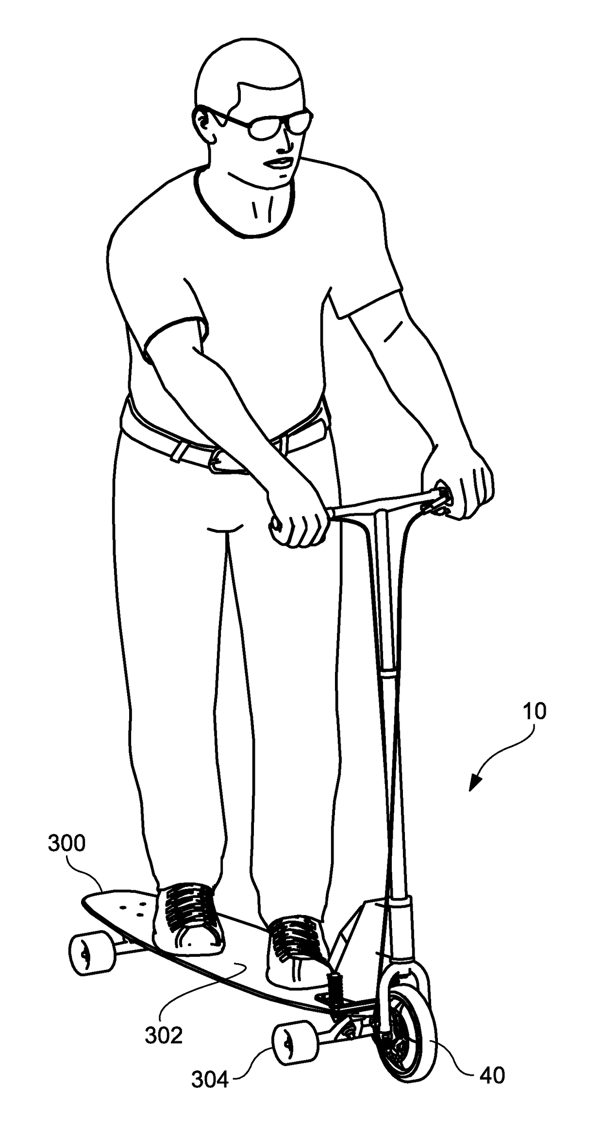
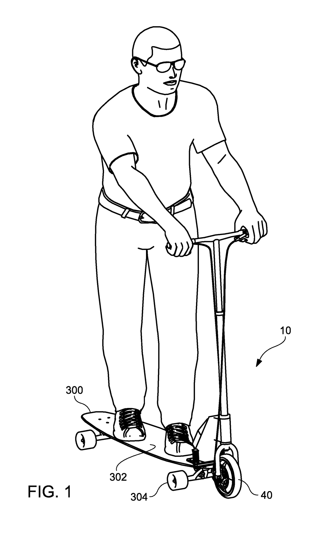
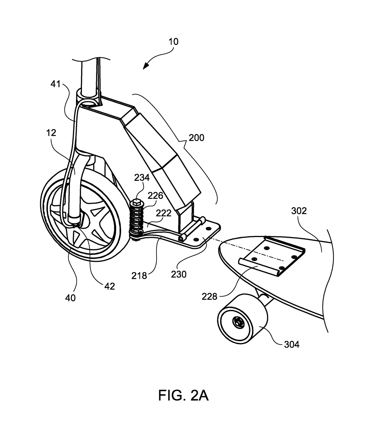
[0043]Referring more specifically to the drawings, for illustrative purposes embodiments of the apparatus for motorized wheel assembly 10 are more completely set forth in FIGS. 1-12

[0044]An embodiment of the motorized wheel assembly 10 adaptable to the front deck 302 of a skateboard 300 having front wheels 304 and rear wheels 308 provides a wheel 60 and axel 62, FIGS. 9A and 9B. The wheel 60 and axel 62 are held within a wheel fork assembly 12 connected to the wheel axel 62. A motor assembly 64 is connected to the wheel 60 with a motor sprocket 66 connected to a fixed length drive chain 70 on a wheel sprocket 68. It will be understood by persons having ordinary skill in the art that the attached skateboard 300 will retain its integral and separate steering mechanism independent of steering from the motorized wheel assembly 10. Mounting the motorized wheel assembly 10 allows use of a large wheel thus increasing the ability to pull the skateboard 300 in a variety of rough or uneven su...


PUM


Abstract

A motorized wheel assembly adaptable to skateboards provides drive motor and power sources and controls for the directed control of forward or backward propulsion of the skateboard using throttle and braking controls, the motorized wheel, and all skateboard wheels. Weight transfer assemblies for the motorized wheel transfer a portion of a skateboard rider's weight through the front mounted motorized wheel to the ground surface creating sufficient traction for the motorized wheel to propel the skateboard. One weight transfer assembly embodiment provides a pivoting, compression based mounting bracket. Separate embodiments of the weight transfer assemblies include single or dual shock absorbers.

Description

CROSS-REFERENCES TO RELATED APPLICATIONS[0001]None.STATEMENT REGARDING FEDERALLY SPONSORED RESEARCH OR DEVELOPMENT[0002]None.REFERENCE TO A MICRO-FICHE APPENDIX[0003]None.TECHNICAL FIELD[0004]The present invention relates generally to a motorized wheel assembly, and more specifically to an electric motorized wheel assembly adaptable to the front deck of a common four-wheel skateboard.BACKGROUND OF THE INVENTION[0005]Motorized skateboards and scooters have gained popularity, ranging from casual commuter riders to those in the extreme end of the action sports community. Many contemporary motorized skateboards and scooters typically are powered by a motor and power supply mounted to the underside of a skateboard or scooter deck. The motor is mechanically linked to a selected one of the rear pair of skateboard wheels or a rear scooter wheel. Other motorized skateboards or scooters use a separate power wheel located between the wheels of the skateboard or scooter.[0006]Disadvantages of t...

Claims


Application Information

Patent Timeline
Patent Type & Authority Patents(United States)
IPC IPC(8): A63C17/12A63C17/14A63C17/01A63C17/00B60L11/18
CPCA63C17/12A63C17/1409A63C17/011A63C17/0013B60L11/1822A63C2017/1472A63C17/012A63C17/1427A63C2203/06A63C2203/12B60L50/60B60L50/66B60L53/80B60L2200/20B60L2200/24B60L2220/46B62K3/002Y02T10/70Y02T10/7072Y02T90/12Y02T90/14
Inventor SARGIS, RAMAN
Owner SARGIS RAMAN
Why Eureka
Try Eureka