

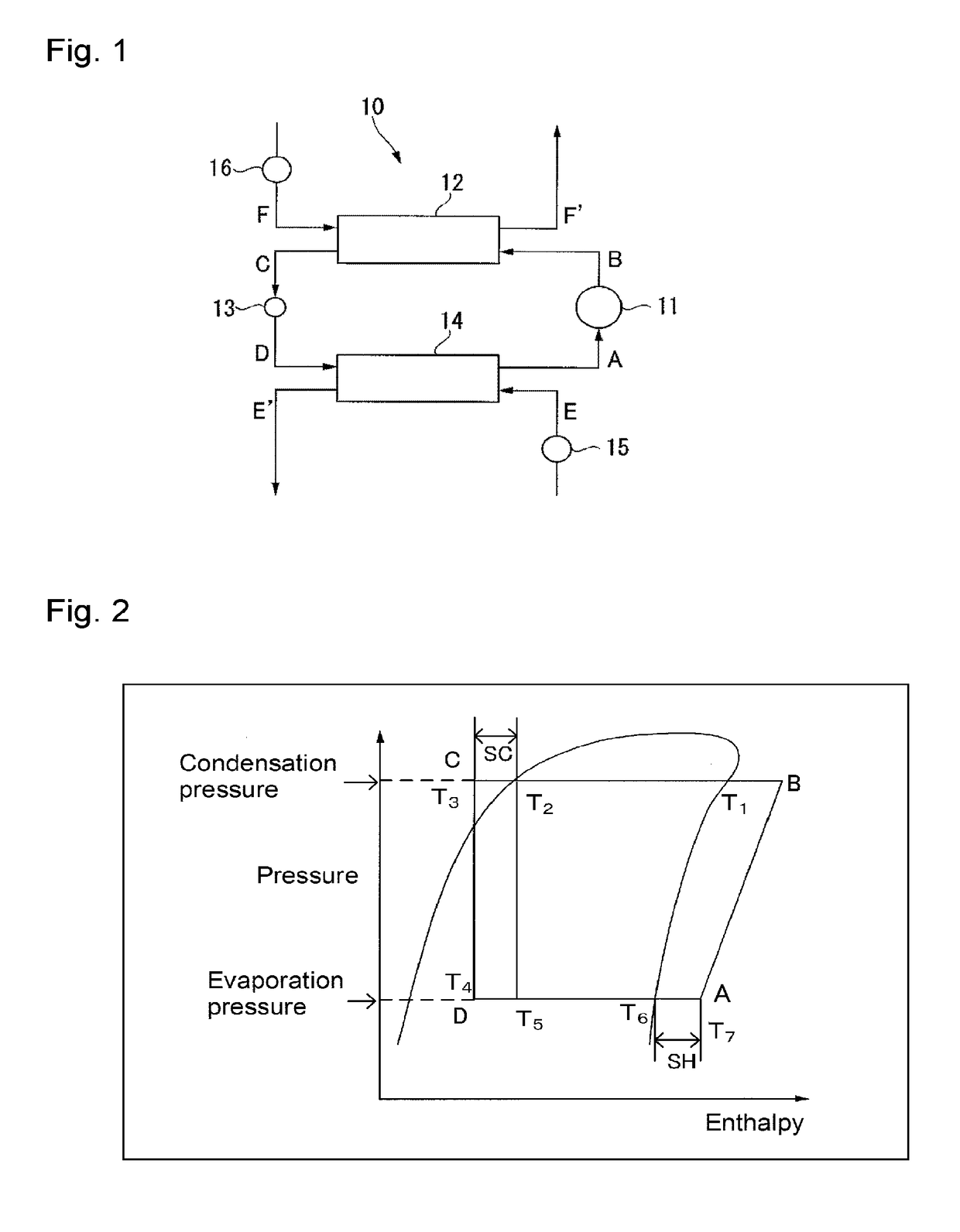
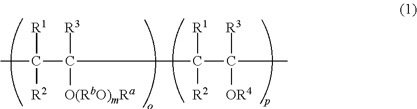
Composition for heat cycle system, and heat cycle system
a heat cycle system and heat cycle technology, applied in the direction of refrigeration components, light and heating equipment, refrigeration machines, etc., can solve the problems of global warming, lower stability of saturated hydrofluorocarbons or hydrochlorofluorocarbons, and reduced lubricating properties in the heat cycle system, so as to achieve stable lubricity of working fluids, excellent cycle performance, and low global warming potential
- Summary
- Abstract
- Description
- Claims
- Application Information
AI Technical Summary
Benefits of technology
Problems solved by technology
Method used
Image

Examples
examples
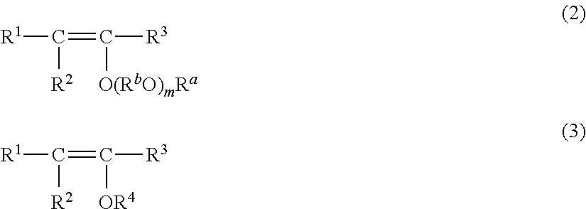
[0280]Now, the present invention will be described in further detail with reference to Examples of the present invention, conventional Examples and Comparative Examples. In each Ex., one of the following working fluids 1 to 64 and one of the following refrigerant oils A to I were selected, 50 g of the working fluid and 50 g of the refrigerant oil were mixed and dissolved to prepare 576 types of composition for a heat cycle system. Accordingly, the composition for a heat cycle system in Ex. is one comprising 50 mass % of the working fluid and 50 mass % of the refrigerant oil. Further, for some working fluids, an antioxidant was added to constitute the composition for a heat cycle system, as described hereinafter.
[0281]The following working fluids and refrigerant oils were used. Compounds constituting the working fluids and the mixture ratios are shown in Table 2, and compounds constituting the refrigerant oils and the mixture ratios are shown in Table 3.
[0282]
TABLE 2[mass %]WorkingHF...
PUM
| Property | Measurement | Unit |
|---|---|---|
| aniline point temperature | aaaaa | aaaaa |
| aniline point temperature | aaaaa | aaaaa |
| breakdown voltage | aaaaa | aaaaa |
Abstract
Description
Claims
Application Information