
Condensate removal device

a technology of condensate removal and condensate, which is applied in the direction of steam traps, solid separation, chemistry apparatus and processes, etc., to achieve the effect of increasing the time period between maintenance inspections

Active Publication Date: 2018-05-01
THERMAL ENERGY INT UK
View PDF7 Cites 1 Cited by
  • Summary
  • Abstract
  • Description
  • Claims
  • Application Information

AI Technical Summary

Benefits of technology

[0008]At its most general, the present invention provides an orifice condensate trap in which a magnet is disposed upstream of the orifice to capture impurities, e.g. magnetic particles, suspended or otherwise carried in the condensable gas or condensate. The magnet may be used in tandem with a mechanical filter, i.e. the magnet may act as a secondary filter, e.g. downstream of a mechanical filter or strainer. Fewer impurities reach the orifice, reducing the likelihood of formation of a partial or complete blockage of the orifice. By capturing debris in this manner, the time period between maintenance inspections can be increased. In particular, the magnet may capture insoluble particulate ferric oxide (or rust particles) which may foul or block the trap and result in damage. In addition, metal ions flowing in the condensate, e.g. copper (II) ions, may be attracted to the magnet. These may be retained once they are stationary on the magnet by the adsorbed ferric oxide.

Problems solved by technology

In particular, the magnet may capture insoluble particulate ferric oxide (or rust particles) which may foul or block the trap and result in damage.

Method used


Image

  • Condensate removal device
  • Condensate removal device
  • Condensate removal device

Examples


Embodiment Construction

; FURTHER OPTIONS AND PREFERENCES

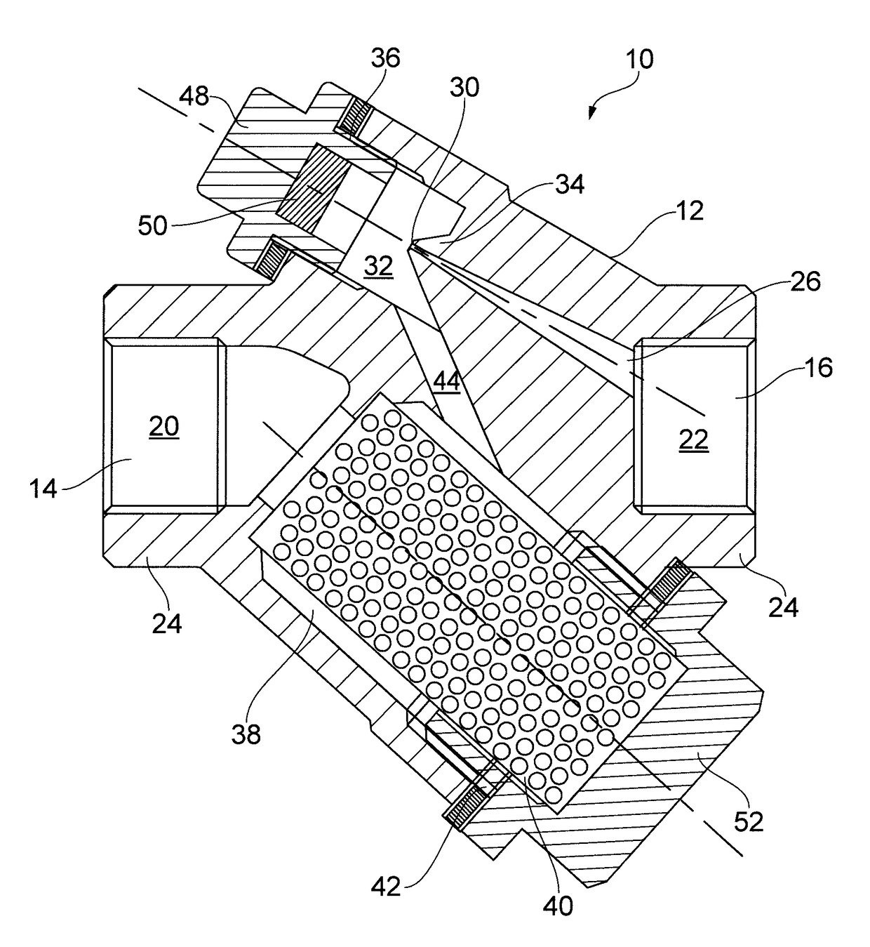
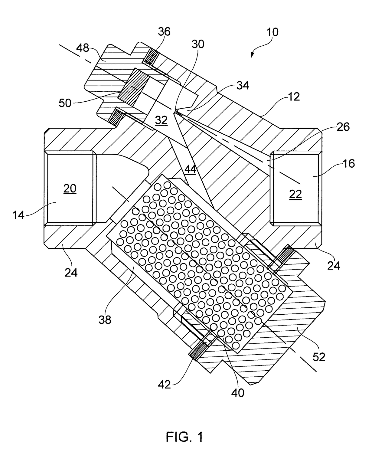
[0051]FIG. 1 shows a condensate removal device (referred to below as a steam trap) 10 according to a first embodiment of the invention.

[0052]The steam trap 10 comprises a unitary body 12 cast from stainless steel or other suitable material. The body 12 has an inlet 14 and an outlet 16 formed on opposite sides thereof. The inlet 14 and outlet 16 are apertures leading into an inlet bored region 20 and an outlet bored region 22 respectively.

[0053]The body 12 is adapted to the connected in a pipeline (not shown). The parts 24 of the body 12 surrounding the inlet 14 and outlet 16 may be arranged to connect to external piping. For example, the parts may be arranged to form any one or more of a screwed, socket weld, and flanged to an adjacent piece of piping. In one embodiment, the parts 24 may be equipped with “quick fit” connectors (also known a pipeline connectors or universal connectors), such as those used on the Emerald Steam Trap manufactured by Ther...


PUM


Abstract

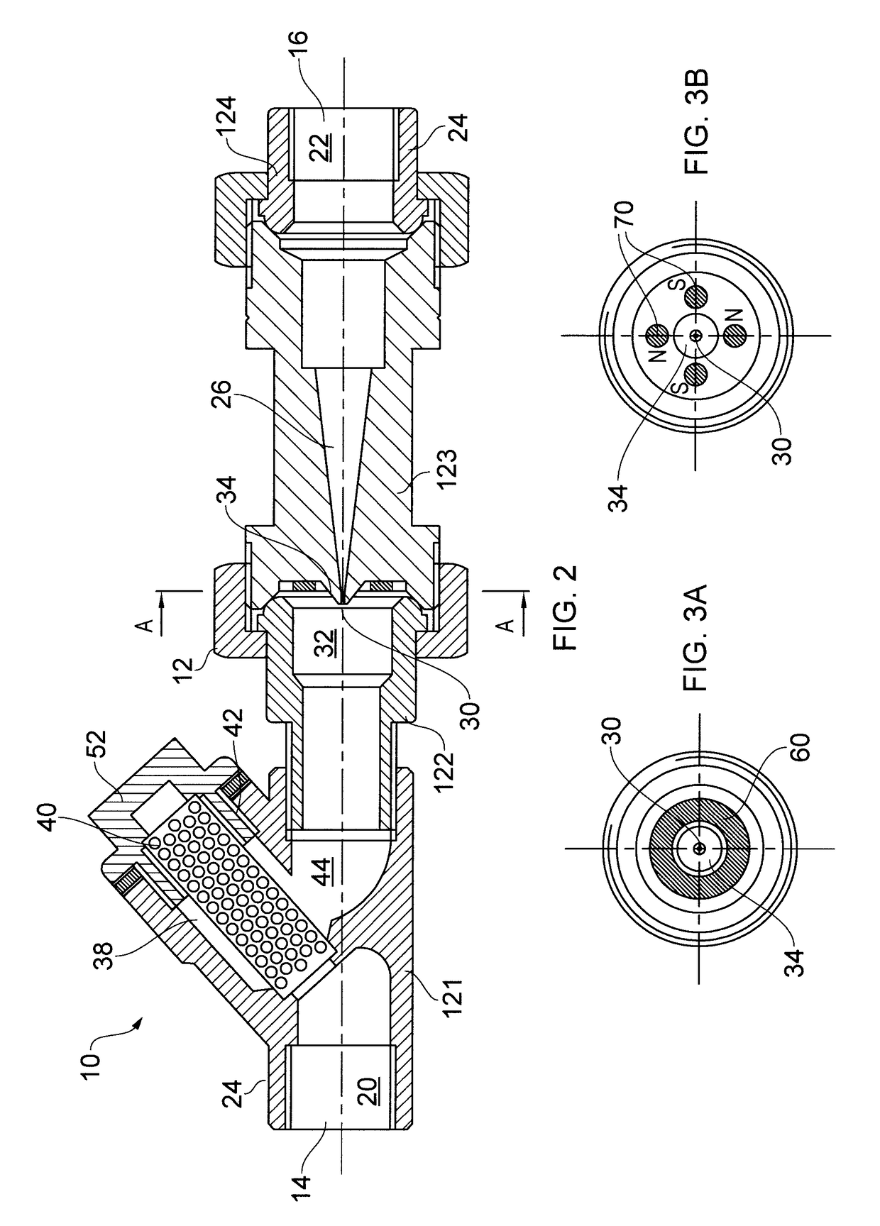
An orifice condensate trap (i.e. a condensate removal device (10) having a condensate drainage channel (26) with a constricted passage (30) therein) in which a magnet (50) is disposed upstream of the orifice to capture impurities, e.g. magnetic particles, suspended or otherwise carried in the condensable gas or condensate. The magnet may be used in tandem with a mechanical filter, e.g. strainer. The magnet may be formed as part of a cap or plug (48) for closing an access opening (36) opposite to an upstream opening of the constricted passage (30). For example, the plug (48) may be formed of magnetic material, e.g. a magnetic variant of stainless steel.

Description

CROSS-REFERENCE TO RELATED APPLICATIONS[0001]This application is a U.S. National Stage Application under 35 U.S.C. § 371 of International Patent Application No. PCT / GB2014 / 050839, filed Mar. 17, 2014, which claims priority to United Kingdom Patent Application No. GB1304935.8, filed Mar. 18, 2013, the contents of which are hereby incorporated by reference in their respective entireties.FIELD OF THE INVENTION[0002]The invention relates to devices for removing liquid condensate from gas-conveyed heat transfer systems whilst restricting gas escape. Such devices are often used for removing condensate from steam-conveying pipelines, where they are known as steam traps.BACKGROUND TO THE INVENTION[0003]Steam is commonly used in industry as a medium for transporting heat energy from a central location via suitable pipelines to its point of use. The heat energy conveyed in the steam may be released at a suitable point by causing a phase change of the steam from as to liquid. The phase change ...

Claims


Application Information

Patent Timeline
Patent Type & Authority Patents(United States)
IPC IPC(8): F16L55/07F16T1/34F16L55/24B03C1/28
CPCF16L55/07B03C1/286F16T1/34F16L55/24B03C2201/18
Inventor MAWBY, SAM
Owner THERMAL ENERGY INT UK
Learn More