Power conversion device

a technology of power conversion device and dc capacitor, which is applied in the direction of power conversion system, dc-ac conversion without reversal, electrical apparatus, etc., can solve the problems of complex multi-transformer, increase in transformer cost, imbalance between voltage of dc capacitor in the positive arm and voltage of dc capacitor in the negative arm, etc., to prevent overvoltage of dc capacitor, stable operation, and reduce calculation amount

Active Publication Date: 2018-05-01
MITSUBISHI ELECTRIC CORP +1
View PDF18 Cites 1 Cited by
  • Summary
  • Abstract
  • Description
  • Claims
  • Application Information

AI Technical Summary

Benefits of technology

[0014]The power conversion device according to the present invention enables reduction in the calculation amount, and can balance voltage of the DC capacitors in the positive arm and voltage of the DC capacitors in the negative arm, thereby preventing overvoltage of the DC capacitors, enabling stable operation even in the case of grid abnormality, and suppressing outflow of harmonics.

Problems solved by technology

However, there is a disadvantage that, in the case where output voltage is high, the configuration of the multiplexed transformer is complicated and the cost of the transformer increases.
Therefore, due to variation among voltages of these DC capacitors, imbalance might occur between voltages of the DC capacitors in the positive arm and voltages of the DC capacitors in the negative arm.

Method used


Image

  • Power conversion device
  • Power conversion device
  • Power conversion device

Examples


embodiment 1

[0023]Hereinafter, a power conversion device 100 according to embodiment 1 of the present invention will be described with reference to the drawings.

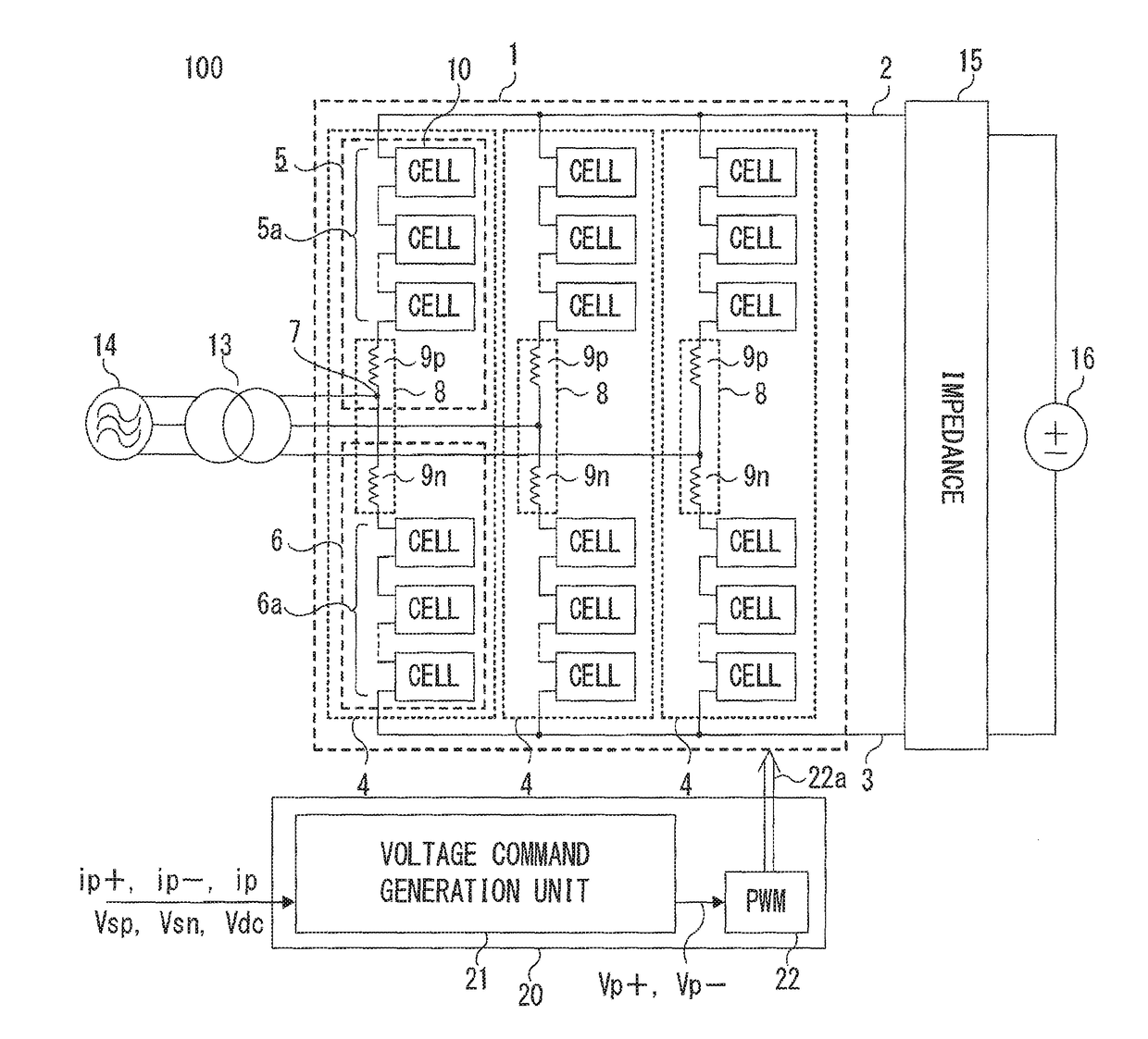
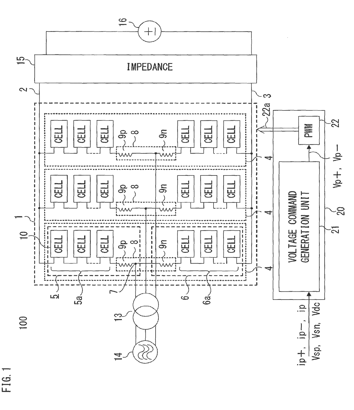
[0024]FIG. 1 is a schematic configuration diagram of the power conversion device 100 according to embodiment 1 of the present invention.

[0025]As shown in FIG. 1, the power conversion device 100 includes a power converter 1 as a main circuit, and a control device 20 for controlling the power converter 1. The power converter 1 performs power conversion between three-phase AC and DC. The AC side of the power converter 1 is connected via an interconnection transformer 13 to a three-phase AC power supply 14 which is a grid as a three-phase AC circuit. The DC side of the power converter 1 is connected via an impedance 15 to a DC power supply 16 which is a DC grid.

[0026]The power converter 1 includes a leg circuit 4 for each phase. Each leg circuit 4 is formed from a positive arm 5 and a negative arm 6 connected in series at an AC terminal 7 w...

embodiment 2

[0114]Hereinafter, with reference to the drawings, embodiment 2 of the present invention will be described focusing on a part different from the above embodiment 1. The same components as those in the above embodiment 1 are denoted by the same reference characters, and the description thereof is omitted.

[0115]FIG. 7 is a block diagram showing the detailed configuration of an arm balance control unit 227 according to embodiment 2 of the present invention.

[0116]The present embodiment and embodiment 1 are different in that, in embodiment 1, the polarity 61a of the zero sequence current in the positive arm 5 and the negative arm 6 is determined from the DC current Idc, whereas, in the present embodiment, the polarity 61a of the zero sequence current in the positive arm 5 and the negative arm 6 is determined and detected from active power P.

[0117]First, in the polarity determination unit 61, the direction of the zero sequence current in the positive arm 5 and the negative arm 6, i.e., th...

embodiment 3

[0121]Hereinafter, with reference to the drawings, embodiment 3 of the present invention will be described focusing on a part different from the above embodiment 1. The same components as those in the above embodiment 1 are denoted by the same reference characters, and the description thereof is omitted.

[0122]FIG. 8 is a block diagram showing the detailed configuration of an arm balance control unit 327 according to embodiment 3 of the present invention.

[0123]A neutral point adjustment value calculation unit 351 according to the present embodiment includes a selection determination unit 80 for comparing the magnitude of the DC current Idc flowing through the power converter 1 with a set threshold value.

[0124]If the magnitude of the DC current Idc is equal to or smaller than the threshold value, the selection determination unit 80 outputs “0” as determination information 80a1, and outputs “1” as determination information 80a2.

[0125]A multiplier 81 multiplies an output 60a of the mult...


PUM


Abstract

A power conversion device includes: a positive arm and a negative arm each of which is formed by connecting a plurality of converter cells in series, the converter cells each being composed of a plurality of semiconductor switching elements and a DC capacitor; and a control circuit. An arm balance control unit in the control circuit calculates a first voltage adjustment value for balancing voltage of the DC capacitors in the positive arm and voltage of the DC capacitors in the negative arm. The control circuit adjusts an AC control command using the first voltage adjustment value, thereby calculating an AC voltage command for AC voltage to be outputted to an AC line for each phase.

Description

TECHNICAL FIELD[0001]The present invention relates to a power conversion device for performing power conversion between a plural-phase AC circuit and a DC circuit, and in particular, relates to a large-capacity power conversion device having a multiplexed converter.BACKGROUND ART[0002]In large-capacity power conversion devices, the converter output is high voltage or large current, and therefore, many large-capacity power conversion devices are configured with a plurality of converters multiplexed in series or parallel. Multiplexing converters allows not only increase in the converter capacity but also reduction in harmonics contained in an output voltage waveform by combining outputs. It is known that, as a result, it is possible to reduce harmonic current flowing out to a grid.[0003]There are various methods for multiplexing converters, e.g., reactor multiplexing, transformer multiplexing, and direct multiplexing. In the case of transformer multiplexing, since an AC side is isolat...

Claims


Application Information

Patent Timeline
Patent Type & Authority Patents(United States)
IPC IPC(8): H02M7/217H02M7/487H02M7/483
CPCH02M7/487H02M2007/4835H02M7/48H02M7/483H02M7/49H02M1/0025H02M1/0074
Inventor MUKUNOKI, KAHOFUJII, TOSHIYUKIUDA, RYOSUKETSUCHIYA, TAICHIROMATSUDA, AKIHIROTAGUCHI, HISANORI
Owner MITSUBISHI ELECTRIC CORP
Why Eureka
Try Eureka