Axial piston machine utilizing a bent-axis construction with a drive joint for driving the cylinder barrel

a technology of axial piston machine and drive joint, which is applied in the direction of mechanical equipment, pumps, liquid fuel engines, etc., can solve the problems of undesirable power loss, increased churning loss, and reduced output power, and achieves the effect of little added construction effort or expens

Inactive Publication Date: 2018-05-08
LINDE HYDRAULICS
View PDF19 Cites 6 Cited by
  • Summary
  • Abstract
  • Description
  • Claims
  • Application Information

AI Technical Summary

Benefits of technology

[0011]This object is accomplished by the invention in that there is a lubrication device for the drive joint, by means of which lubricant is delivered to the drive body by a lubricant port located on the housing of the axial piston machine for the cooling and lubrication of the drive body. With a lubrication device of this type for the drive joint, it is possible in a simple manner and with little extra construction effort or expense to supply the drive bodies of the drive joint with lubricant, such as hydraulic fluid, which is delivered via a lubricant port on the housing of the axial piston machine. During operation of the axial piston machine with a housing that has been emptied of hydraulic fluid, sufficient cooling and lubrication of the drive bodies of the drive joint for the operation of the machine, in particular at high speeds of rotation, is provided by the lubricant delivered via the lubrication device.
[0012]Supply of the drive bodies of the drive joint with lubricant that is delivered via the lubricant port on the housing can be ensured with little extra construction effort or expense if the lubrication device is located in the drive shaft and has a lubricant channel located in the drive shaft. When the axial piston machine is operated with a housing that has been emptied of hydraulic fluid, lubricant is transported from the lubricant port on the housing to the drive bodies of the drive joint in a simple manner via the lubricant channel located in the drive shaft.
[0013]In one advantageous embodiment of the invention, the lubricant channel has a lubricant supply boring located in the drive shaft and which is in connection with the lubricant port. At least one lubrication boring is located in the drive shaft and is connected to the lubricant supply boring and extends to the peripheral surface of the drive shaft and is provided in the peripheral surface with an opening. The opening of the lubrication boring in the peripheral surface is located and oriented such that when the drive shaft is in rotation, the lubricant delivered via the lubricant supply boring and the lubrication boring flows to the drive bodies by the action of centrifugal force. To supply the drive bodies of the drive joint with lubricant, a lubricant supply boring is introduced into the drive shaft of the axial piston machine. For each drive body, a transverse boring in the form of a lubricant boring is connected to this lubricant supply boring, which lubrication boring is located in the drive shaft and is provided on the external periphery of the drive shaft with an opening, through which the lubricant delivered by the lubricant supply boring can be discharged and can flow directly onto the corresponding drive bodies of the drive joint. A lubricant supply boring and corresponding lubrication borings in the form of transverse borings can be made in the drive shaft of the axial piston machine with little extra construction effort or expense. When the drive shaft is in rotation, lubricant can therefore flow by centrifugal force to the drive bodies so that when the drive shaft is in rotation, the drive bodies are lubricated and cooled by the lubricant that is supplied via the lubricant supply boring and the lubrication boring.

Problems solved by technology

During operation of the axial piston machine with a rotating drive shaft and rotating cylinder barrel, this arrangement results in churning losses that increase extra-proportionally as the speed of rotation increases.
These churning losses represent an additional consumption of energy, which in an axial piston machine in the form of a pump must be compensated for by the drive system and result in an undesirable power loss, or in an axial piston machine in the form of a motor resulting in a lower output power.
In particular, at high speeds of rotation of the rotating components, this power loss can be of a significant magnitude, as a result of which the efficiency and potential applications of axial piston machines at high speeds of rotation are limited and restricted.
In a hydrostatic axial piston machine and with a housing emptied of hydraulic fluid, however, sufficient cooling and lubrication of the drive bodies of the drive joint are no longer guaranteed.

Method used


Image

  • Axial piston machine utilizing a bent-axis construction with a drive joint for driving the cylinder barrel
  • Axial piston machine utilizing a bent-axis construction with a drive joint for driving the cylinder barrel
  • Axial piston machine utilizing a bent-axis construction with a drive joint for driving the cylinder barrel

Examples


Embodiment Construction

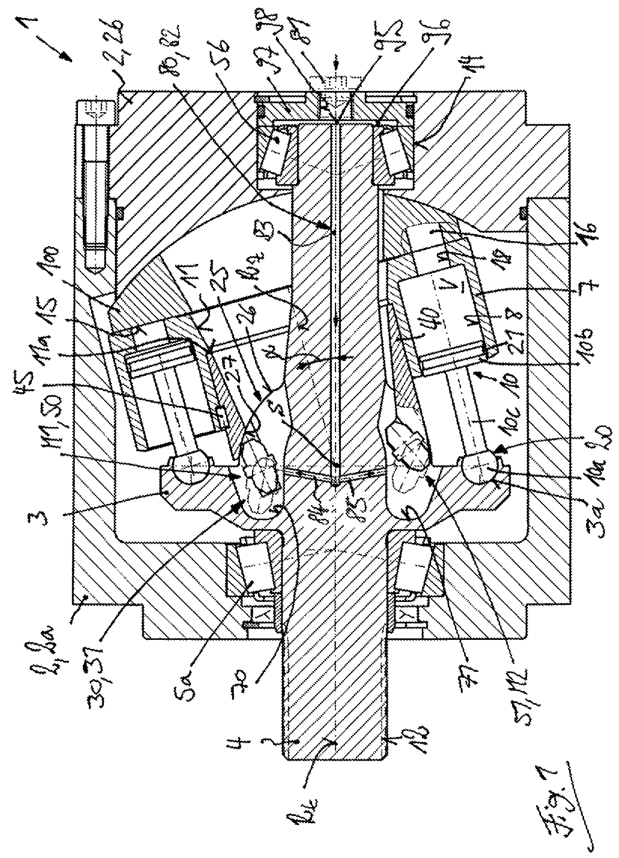
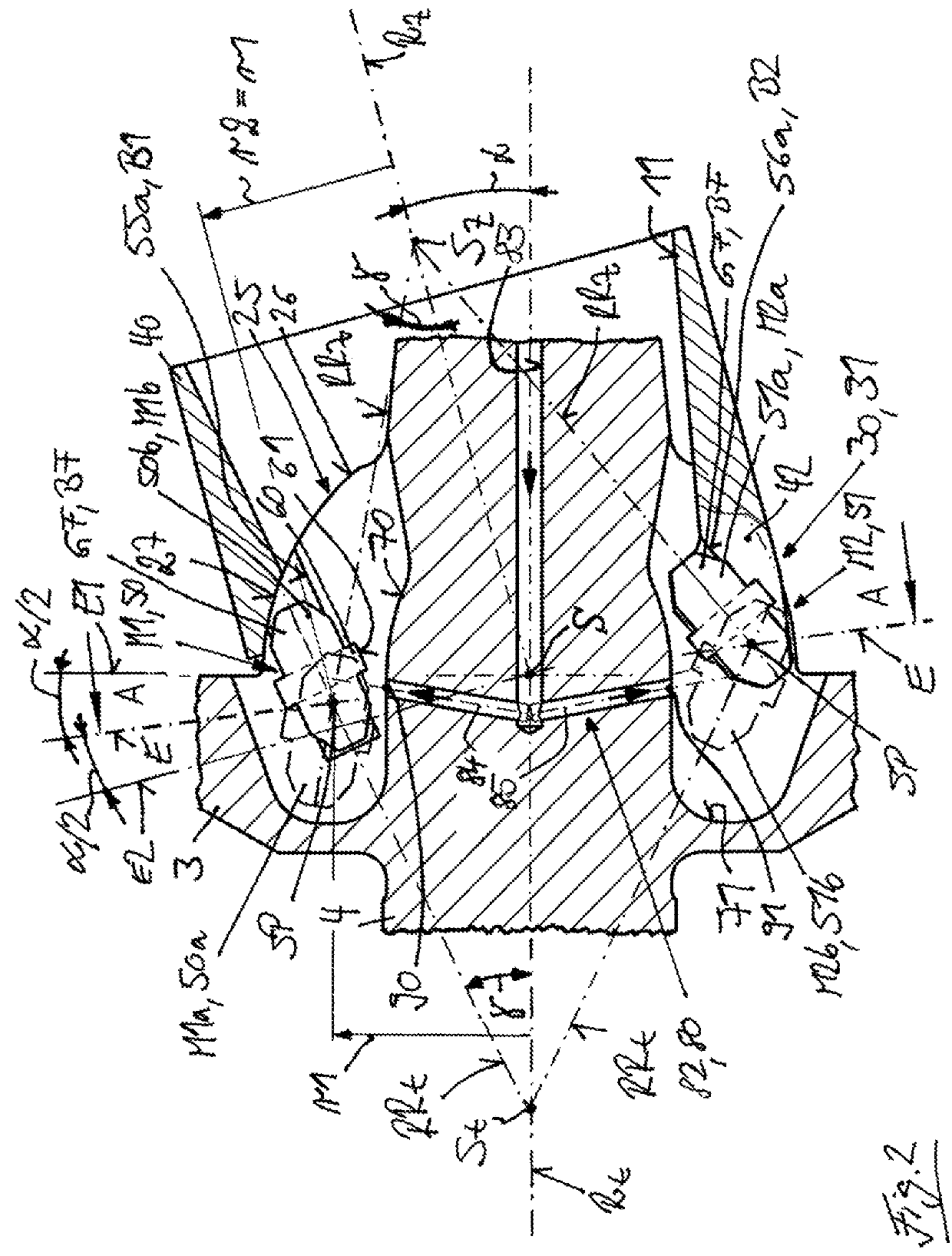
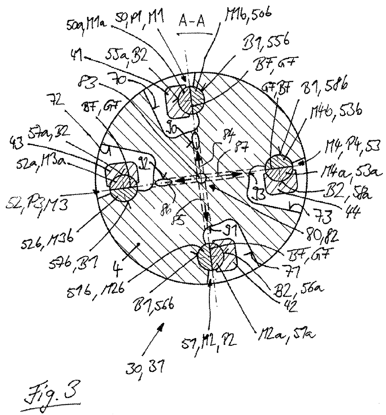
[0037]A hydrostatic axial piston machine 1 of the invention utilizing a bent-axis construction is illustrated in FIGS. 1 to 3. The machine 1 has a housing 2 that includes a housing barrel 2a and a housing cover 2b. A drive shaft 4 having a drive flange 3 is mounted in the housing 2 by means of bearing devices 5a, 5b so that it can rotate around an axis of rotation Rt. In the illustrated exemplary embodiment, the drive flange 3 is formed in one piece on the drive shaft 4.

[0038]Located in the housing 2 axially next to the drive flange 3 is a cylinder barrel 7 which rotates around an axis of rotation RZ and has a plurality of piston bores 8, which in the illustrated exemplary embodiment are arranged concentrically around the axis of rotation RZ of the cylinder barrel 7. A longitudinally displaceable piston 10 is located in each piston bore 8.

[0039]The axis of rotation Rt of the drive shaft 4 intersects the axis of rotation RZ of the cylinder barrel 7 at the intersection point S.

[0040]T...


PUM


Abstract

A hydrostatic axial piston machine (1) utilizing a bent-axis construction has a drive shaft (4) with a drive flange (3) rotatable around an axis of rotation (Rt) inside a housing (2). A cylinder barrel (7) is located inside the housing (2) and is rotatable around an axis of rotation (RZ). A drive joint (30) is located between the drive shaft (4) and the cylinder barrel (7). The drive joint (30) has at least one drive body (M1; M2; M3; M4) in the form of a slider or a roller body which is supported in the drive shaft (4) and the cylinder barrel (7). A lubrication device (80) is provided for the drive joint (30) and supplies lubricant from a lubricant port (81) located on the housing (2) of the axial piston machine (1) to the drive bodies (M1; M2; M3; M4) for cooling and lubrication of the drive bodies (M1; M2; M3; M4).

Description

CROSS REFERENCE TO RELATED APPLICATIONS[0001]This application claims priority to German Application No. DE102014104953.5 filed Apr. 8, 2014, which is herein incorporated by reference in its entirety.BACKGROUND OF THE INVENTION[0002]Field of the Invention[0003]This invention relates to a hydrostatic axial piston machine utilizing a bent-axis construction having a drive shaft located inside a housing and rotatable around an axis of rotation. The drive shaft has a drive flange. A cylinder barrel is located inside the housing of the axial piston machine and rotates around an axis of rotation. The cylinder barrel has a plurality of piston bores. A longitudinally displaceable piston is located in each piston bore. The pistons are fastened to the drive flange in an articulated manner. A drive joint for driving the cylinder barrel is located between the drive shaft and the cylinder barrel. The drive joint has at least one drive body in the form of a slider or roll body which is supported on...

Claims


Application Information

Patent Timeline
Patent Type & Authority Patents(United States)
IPC IPC(8): F01B3/00F04B1/20F04B53/18F03C1/06F04B27/10
CPCF01B3/0032F01B3/0082F04B1/20F04B53/18F03C1/0636F04B27/109
Inventor BERGMANN, MARTINKAUSCH, SABINE
Owner LINDE HYDRAULICS
Why Eureka
Try Eureka