Method for monitoring a heat exchanger unit

a heat exchanger and monitoring method technology, applied in the direction of lighting and heating apparatus, instruments, and semiconductor/solid-state device details, etc., can solve the problems of low thermal conductivity, deterioration of the capacity of the surface of the fin to transfer heat, and blown radiators

Inactive Publication Date: 2018-05-15
FORUM US
View PDF28 Cites 18 Cited by
  • Summary
  • Abstract
  • Description
  • Claims
  • Application Information

AI Technical Summary

Problems solved by technology

Over time airborne dirt in and other particulate in the air will begin to deposit on the air intake side (and elsewhere), resulting in a fouled radiator.
Fouling can seriously deteriorate the capacity of the surface of the fins to transfer heat under the conditions for which they were designed.
Among other problems, the fouling layer has a low thermal conductivity which increases the resistance to heat transfer and reduces the effectiveness of heat exchangers.
In addition, fouling reduces the cross-sectional area in the passageways, which causes an increase in pressure drop across a heat exchanger.
Radiator fouling affects both capital and operating costs of heat exchangers (and overall processes).
Higher capital expenditures include that for excess surface area (for heat transfer), extra space, and transport and installation costs.
Operating expenditures include that for energy losses due to the decrease in thermal efficiency, increases in the pressure drop through process equipment, and production losses during planned and unplanned plant shutdowns for fouling cleaning.
Moreover, government emissions regulations are forcing engine manufacturers and their customers to reduce emissions from reciprocating engines.
In summary, fouling of heat transfer surfaces is one of the most important problems in heat transfer equipment.
Some have described fouling as the major unresolved problem in heat transfer.
One of the highest maintenance costs any piece of equipment has is cooling system maintenance.
This approach relies on extensive cost and resource being allocated toward the antiquated philosophy of operational redundancy.

Method used


Image

  • Method for monitoring a heat exchanger unit
  • Method for monitoring a heat exchanger unit
  • Method for monitoring a heat exchanger unit

Examples


Embodiment Construction

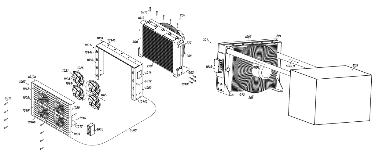
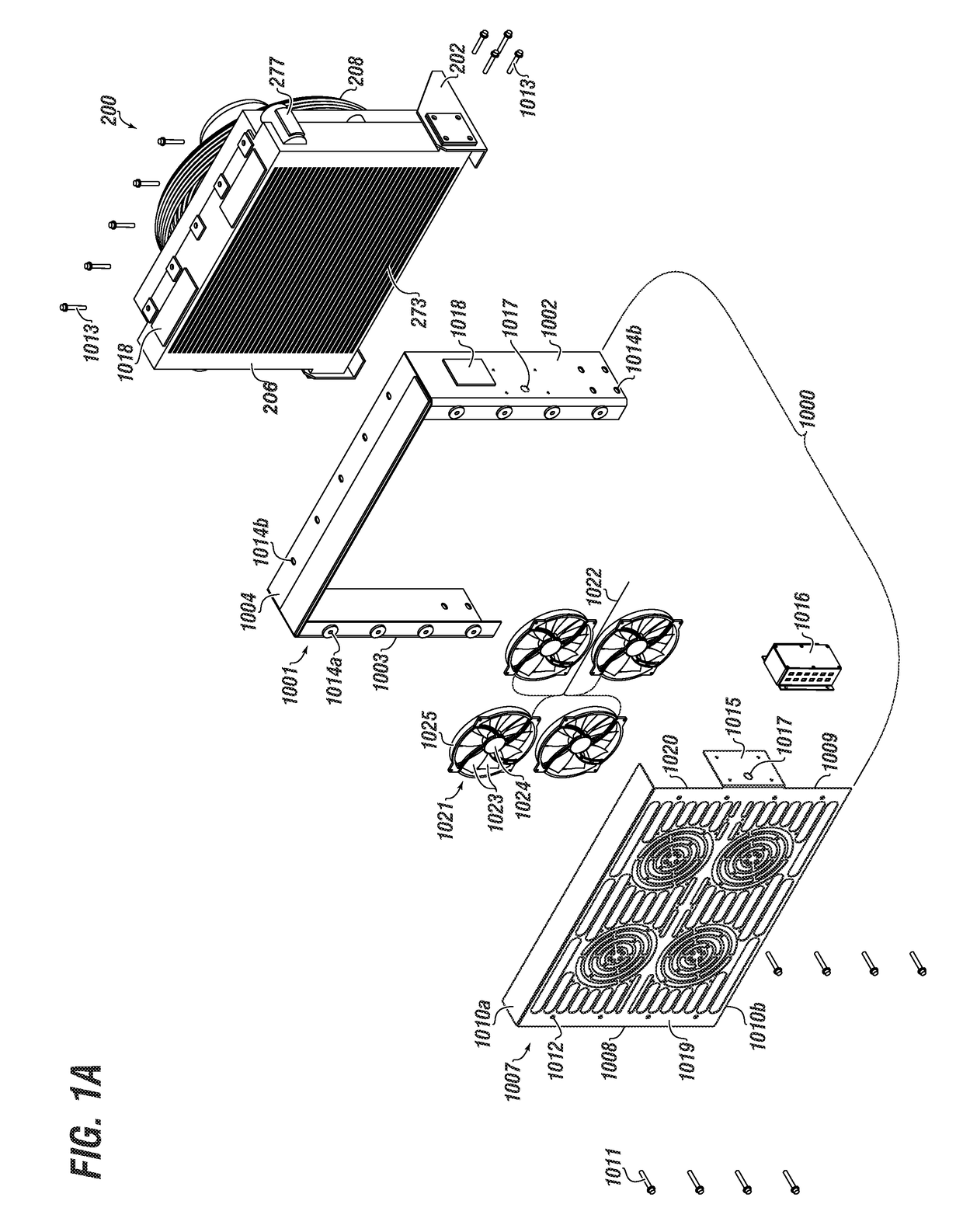
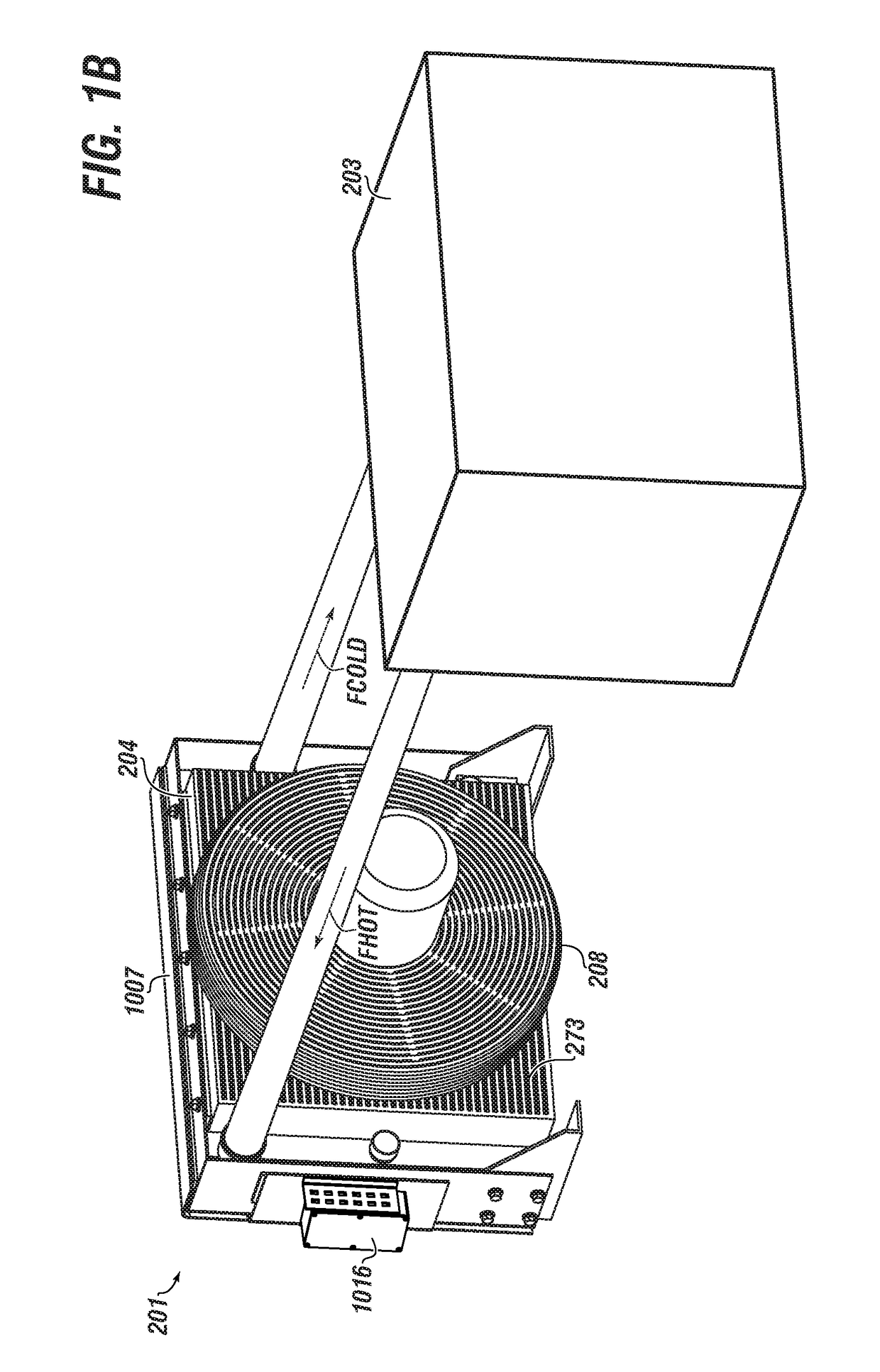
[0056]Herein disclosed are novel apparatuses, systems, and methods that pertain to an improved heat exchanger, details of which are described herein.

[0057]Embodiments of the present disclosure are described in detail with reference to the accompanying Figures. In the following discussion and in the claims, the terms “including” and “comprising” are used in an open-ended fashion, such as to mean, for example, “including, but not limited to . . . ”. While the disclosure may be described with reference to relevant apparatuses, systems, and methods, it should be understood that the disclosure is not limited to the specific embodiments shown or described. Rather, one skilled in the art will appreciate that a variety of configurations may be implemented in accordance with embodiments herein.

[0058]Although not necessary, like elements in the various figures may be denoted by like reference numerals for consistency and ease of understanding. Numerous specific details are set forth in order ...


PUM


Abstract

Embodiments of the disclosure pertain to a method for monitoring a heat exchanger unit that may include the steps of: associating a monitoring module with an airflow side of the heat exchanger unit; operating the monitoring module whereby a microcontroller performs tasks related to data acquisition, data comparison, and providing an indication; and taking an action based on the indication. The monitoring module includes an at least one sensor proximate to the airflow side; a logic circuit in operable communication with the at least one sensor, and further comprising the microcontroller.

Description

CROSS-REFERENCE TO RELATED APPLICATIONS[0001]This application is a continuation of U.S. non-provisional application Ser. No. 15 / 591,086, filed May 9, 2017, which is a continuation-in-part of U.S. non-provisional application Ser. No. 15 / 477,097, filed Apr. 2, 2017, which claims the benefit under 35 U.S.C. § 119(e) of U.S. Provisional Patent Application Ser. No. 62 / 320,606, filed on Apr. 10, 2016, and of U.S. Provisional Patent Application Ser. No. 62 / 320,611, filed on Apr. 10, 2016. The entirety of each application is incorporated herein by reference in entirety for all purposes.INCORPORATION BY REFERENCE[0002]The subject matter of co-pending U.S. non-provisional application Ser. Nos. 15 / 477,097 and 15 / 477,100, each filed Apr. 2, 2017, is incorporated herein by reference in entirety for all purposes.STATEMENT REGARDING FEDERALLY SPONSORED RESEARCH OR DEVELOPMENT[0003]Not Applicable.BACKGROUND[0004]Field of the Disclosure[0005]This disclosure generally relates to a heat exchanger unit...

Claims


Application Information

Patent Timeline
Patent Type & Authority Patents(United States)
IPC IPC(8): F22B37/00F28F27/00H01L23/467F28G15/00F28D1/04F28D1/02B60K11/08F28D21/00F04D19/00G06F1/20
CPCF28G15/003F28F27/00G06F1/206H01L23/467B60K11/08G06F1/20F28D1/024F28D1/04F28D2021/008F28D2021/0031F28D2021/0091F04D19/002F04D25/068F04D25/166B60K11/02
Inventor VANBERG, RANDYZAREIE RAJANI, HAMID REZALARIMI, SEYED REZAABBASI, MORTEZA
Owner FORUM US
Why Eureka
Try Eureka